IMPORTANT
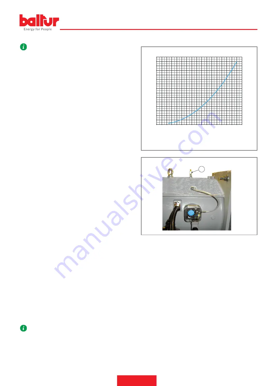
This method permits only an approximate estimate of the
combusted thermal flow rate delivered, for a precise measuring,
refer to gas meter.
Example
•
Burner
• Ptc = Pressure measured on port G:
•
Pcc = Back pressure measured in the furnace:
•
Head pressure value without the back pressure in the furnace: P
= Ptc - Pcc
From the diagram, in correspondence of pressure "P", the combusted
thermal input of about "X" can be inferred.
POWER AT START-UP
The standard EN 676 prescribes that for burners with maximum output
above 120 kW the ignition must occur at a reduced power
Pstart
than the maximum power of operation
Pmax
at which the burner is
calibrated.
Pstart
depends on the safety time of the burner equipment; in par
-
ticular:
ts = 2s →
Pstart
≤ 0.5
x
Pmax
.
ts = 3s →
Pstart
≤ 0.333 x
Pmax
.
Example
if the maximum regulation power of the burner
Pmax
is
equal to 900 kW, it must be:
Pstart
≤ 450 kW where ts = 2s
Pstart
≤ 300 kW where ts = 3s
Check power at ignition
•
Disconnect the flame sensor wire (in this case the burner turns on
and goes into lock-out after the safety time ts).
•
Perform 10 consecutive ignitions and following block.
•
Measure at the meter the amount of gas burned
Qstart
[m³]
and check that
Qstart ≤ Pmax /360
( in m³/h)
Example
Pmax = 90 m³/h (about 900 kW with natural gas)
After 10 ignitions with the related lock out, the gas consumption read
on the meter must be:
Qstart
≤ 90/360 = 0.25 [m³]
If this does not occur, reduce the flow of gas to the ignition through the
brake of the valve.
REGULATION AFTER THE BURNER CALIBRATION:
The pressure switches are connected so that the triggering (opening of
the circuit) of any of the pressure switches when the burner is running
(flame on), locks out the burner immediately.
The minimum value pressure switch stops the burner that remains on
standby until the pressure is restored within the values required for
operation.
After that, the burner re-starts in an autonomous way following the igni
-
tion sequence.
IMPORTANT
In case only one pressure switch is installed on the gas train, it
must be a pressure switch for minimum pressure.
HEAD LOSSES ON GAS SIDE
0
10
20
30
40
50
60
70
80
90
100
110
120
130
140
150
0 1 2 3 4 5 6 7 8 9 10 11 12 13 14 15 16 17
mbar / hPa
kW x 1000
0002570290N4
P
X
(X)
Power (kW)
(P)
Head gas net pressure (mbar)
pr
esapr
ess_TBMLME
G
27 / 40
0006160375_202305
ENGLISH
Summary of Contents for TBML 1600 ME
Page 2: ......
Page 37: ...SCHEMI ELETTRICI TBML 1200ME 1600ME 2000ME BT 335 35 40 0006160375_202305 ITALIANO ...
Page 38: ...TBML 1200ME 1600ME 2000ME BT 335 36 40 0006160375_202305 ITALIANO ...
Page 39: ...TBML 1200ME 1600ME 2000ME BT 335 37 40 0006160375_202305 ITALIANO ...
Page 40: ...TBML 1200ME 1600ME 2000ME BT 335 38 40 0006160375_202305 ITALIANO ...
Page 41: ...BA I1 I2 I3 I4 TBML 1200ME 1600ME 2000ME BT 335 39 40 0006160375_202305 ITALIANO ...
Page 77: ...WIRING DIAGRAMS TBML 1200ME 1600ME 2000ME BT 335 35 40 0006160375_202305 ENGLISH ...
Page 78: ...TBML 1200ME 1600ME 2000ME BT 335 36 40 0006160375_202305 ENGLISH ...
Page 79: ...TBML 1200ME 1600ME 2000ME BT 335 37 40 0006160375_202305 ENGLISH ...
Page 80: ...TBML 1200ME 1600ME 2000ME BT 335 38 40 0006160375_202305 ENGLISH ...
Page 81: ...BA I1 I2 I3 I4 TBML 1200ME 1600ME 2000ME BT 335 39 40 0006160375_202305 ENGLISH ...
Page 83: ......


