ENGLISH
35 / 54
0006081544_201907
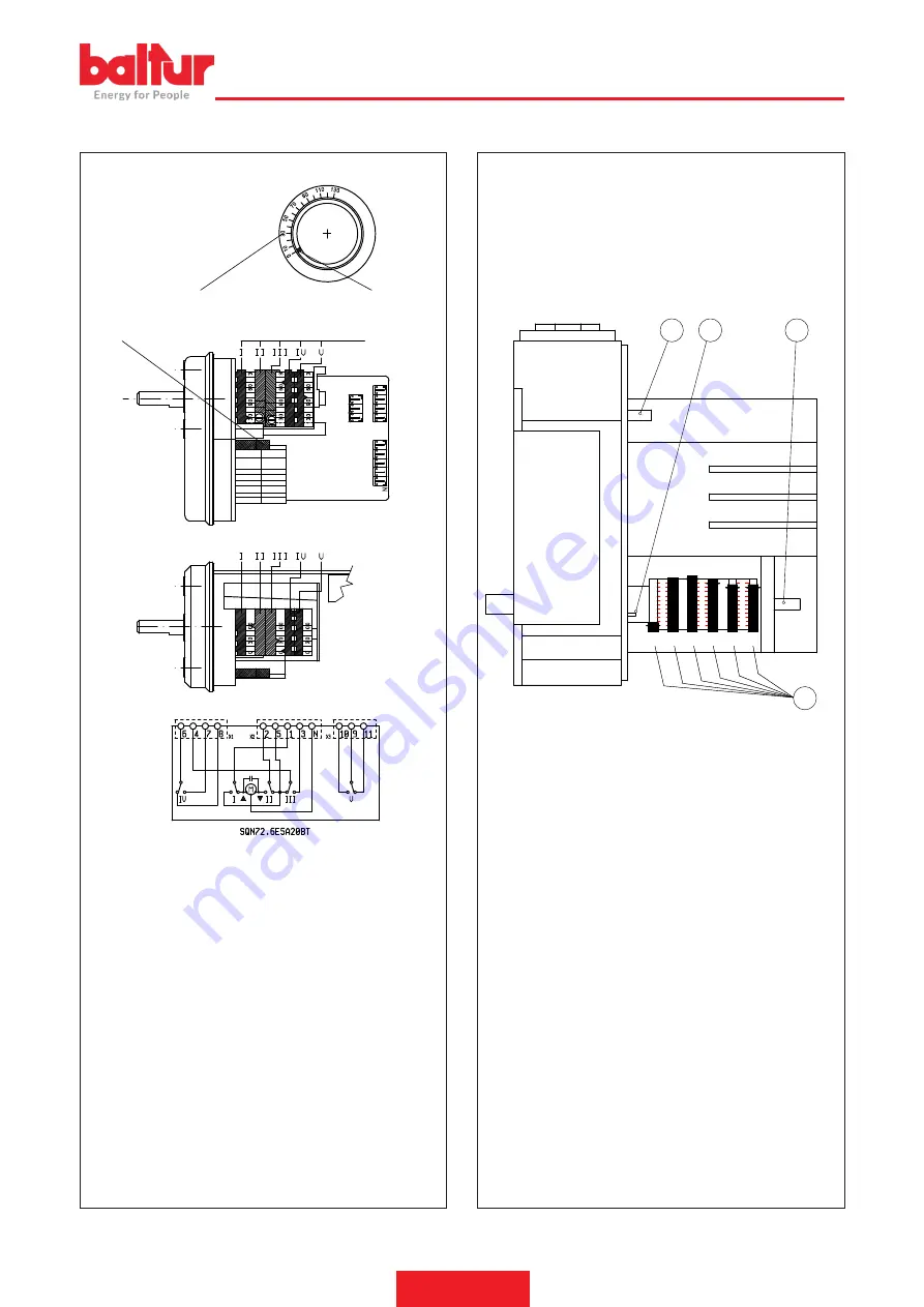
SERVOMOTOR CAM ADJUSTMENT SQN72.6E5A20BT
0002937920
A
B
C
D
A Reference scale
B Position indicator
C Camshaft-motor coupling enabling/disabling pin
D Adjustable cams
I Adjustment cam for maximum air opening (130°)
II Total air closure (burner stopped) (0°)
III Air regulation cam for gas minimum (30°)
IV 1st flame diesel oil adjustment cam (50°)
V Ignition transformer activation cam (40°)*
Use the corresponding rings to modify the adjustment of the
utilized cams (I - II - III....). The index of the ring indicate on the
respective reference scale the rotation angle taken up for each
cam.
CAM ADJUSTMENT OF SERVOMOTOR SQM 40...
135
90
60
30
II III IV
I
135
90
60
30
135
90
60
30
V
VI
0002939370
1
2
3
4
1 On/Off lever for motor-camshaft coupling
2 Reference scale
3 Camshaft
4 Adjustable camshaft
I Maximum air opening (130°)
II Air regulation cam for gas minimum (30°) (<IV)
III Air regulation cam for diesel minimum (90°) (>V)
IV Gas ignition air opening (40°)
V Diesel ignition air opening (80°)
VI 2nd diesel flame valve control cam (110°)
To modify the adjustment of the cams operate the respective
screws.The pointer on the red ring indicates the rotation angle
set for each cam on the respective reference scale.
Summary of Contents for TBML 200 MC
Page 2: ......
Page 48: ...ITALIANO 46 54 0006081544_201907 SCHEMI ELETTRICI ...
Page 49: ...ITALIANO 47 54 0006081544_201907 ...
Page 50: ...ITALIANO 48 54 0006081544_201907 ...
Page 52: ...ITALIANO 50 54 0006081544_201907 ...
Page 53: ...ITALIANO 51 54 0006081544_201907 ...
Page 54: ...ITALIANO 52 54 0006081544_201907 ...
Page 56: ...ITALIANO 54 54 0006081544_201907 ...
Page 102: ...ENGLISH 46 54 0006081544_201907 WIRING DIAGRAMS ...
Page 103: ...ENGLISH 47 54 0006081544_201907 ...
Page 104: ...ENGLISH 48 54 0006081544_201907 ...
Page 106: ...ENGLISH 50 54 0006081544_201907 ...
Page 107: ...ENGLISH 51 54 0006081544_201907 ...
Page 108: ...ENGLISH 52 54 0006081544_201907 ...
Page 110: ...ENGLISH 54 54 0006081544_201907 ...
Page 111: ......


