ENGLISH
27 / 44
0006160028_201510
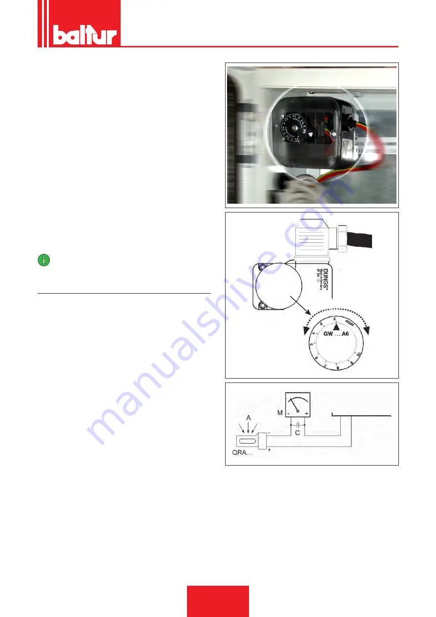
Adjust the setting of the pressure switch to a level slightly below
the actual air pressure detected in first stage operation. Reset the
burner and check that it starts up correctly.
GAS PRESSURE CONTROL PRESSURE-SWITCHES
The gas pressure switches (minimum and maximum) prevent
the burner from operating when gas pressure is not between the
expected range.
The minimum value pressure switch makes use of the NO (nor-
mally open) contact which is closed when the pressure switch de-
tects a pressure higher than its own setting.
The maximum pressure switch makes use of the NC (normally
closed) contact which is closed when the pressure switch detects
a pressure lower than its own setting.
Adjustment of minimum and maximum pressure values on the
pressure switches must be performed when testing the burner, on
the basis of the pressure measured in each case.
The triggering (opening of the circuit) of any of the pressure swi-
tches when the burner is running (flame on) causes the burner to
stop immediately.
When first switching on the burner it is essential to check that it
works properly.
IMPORTANT
In case only one pressure switch is installed on the gas
train, it must be a pressure switch for minimum pressure.
FLAME DETECTION CURRENT
The minimum flame detection current value required for a correct
operation of the equipment is indicated in the wiring diagram.
The burner provides a significantly higher current and therefore
does not normally require any checks at all.
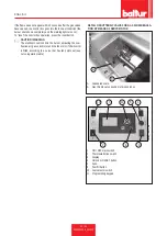
If flame detection current has to be measured, it is necessary to
connect a microammeter in series to the photocell cable.
BT 3..
x21/2
Summary of Contents for TBML 50 ME
Page 2: ......
Page 40: ...SCHEMI ELETTRICI ITALIANO 38 44 0006160028_201510...
Page 41: ...ITALIANO 39 44 0006160028_201510...
Page 42: ...ITALIANO 40 44 0006160028_201510...
Page 43: ...ITALIANO 41 44 0006160028_201510...
Page 44: ...BT1 BA BP I1 I2 I3 I4 ITALIANO 42 44 0006160028_201510...
Page 46: ...ITALIANO 44 44 0006160028_201510...
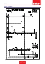
Page 84: ...ENGLISH 38 44 0006160028_201510 WIRING DIAGRAMS...
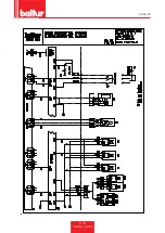
Page 85: ...ENGLISH 39 44 0006160028_201510...
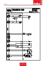
Page 86: ...ENGLISH 40 44 0006160028_201510...
Page 87: ...ENGLISH 41 44 0006160028_201510...
Page 88: ...ENGLISH 42 44 0006160028_201510 BT1 BA BP I1 I2 I3 I4...
Page 90: ...ENGLISH 44 44 0006160028_201510...
Page 91: ......


