10
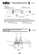
N° BT 8910/2
rev. 31/05/01
HYDRAULIC DIAGRAM TO THE BURNERS
GI 1000 - TS - PYR OPERATING WITH THICK
HEAVY OIL (50 °E AT 50 °C)
WITH AUXILIARY HEATER
1
- Filter
2
- Circulating pumps (one spare)
3
- Start-up resistance with thermostat
4
- Burner pushung central station
5
- Steam or hot water coil to heat oil
6
- Auxiliary heater
7
- Main tank
8
- Steam or hot water heating to keep the oil at a
temperature at which it can flow through the
pipes, even while the machine is down
9
- Degasifier (Ø = 100 - H = 300)
10
- Thermometer
Heating electric cable
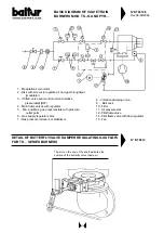
N° BT 8911/1
rev. 30/05/01
HYDRAULIC DIAGRAM TO THE BURNER GI 1000 - TS - PYR OPERATING WITH
LIGHT OIL OR HEAVY OIL WITH MAX. NOMINAL VISCOSITY 5 °E AT 50°C
1
- Filter
2
- Circulation pumps (one spare)
3
- Burner pushing central station
4
- Main tank
5
- Oil heating at steam or at hot water in order to keep,
also during a short period of non operation, a temperature
value sufficient for the flow in the piping
Summary of Contents for TS 0 GN
Page 2: ......
Page 47: ......
Page 48: ......
Page 49: ......
Page 50: ......
Page 51: ......
Page 52: ......
Page 53: ......
Page 54: ......
Page 55: ......
Page 56: ......
Page 57: ......
Page 58: ......
Page 59: ......
Page 60: ......
Page 61: ......
Page 62: ......
Page 63: ......
Page 64: ......
Page 65: ......
Page 66: ......
Page 67: ......
Page 68: ......
Page 69: ......
Page 70: ......
Page 71: ......
Page 72: ......
Page 73: ......
Page 74: ......
Page 75: ......
Page 76: ......
Page 77: ......
Page 78: ......
Page 79: ......
Page 80: ......
Page 81: ......
Page 82: ......
Page 83: ......
Page 84: ......
Page 85: ......
Page 86: ......
Page 87: ......
Page 88: ......
Page 89: ......
Page 90: ......
Page 91: ......
Page 92: ......
Page 93: ......
Page 94: ......
Page 95: ......


