33
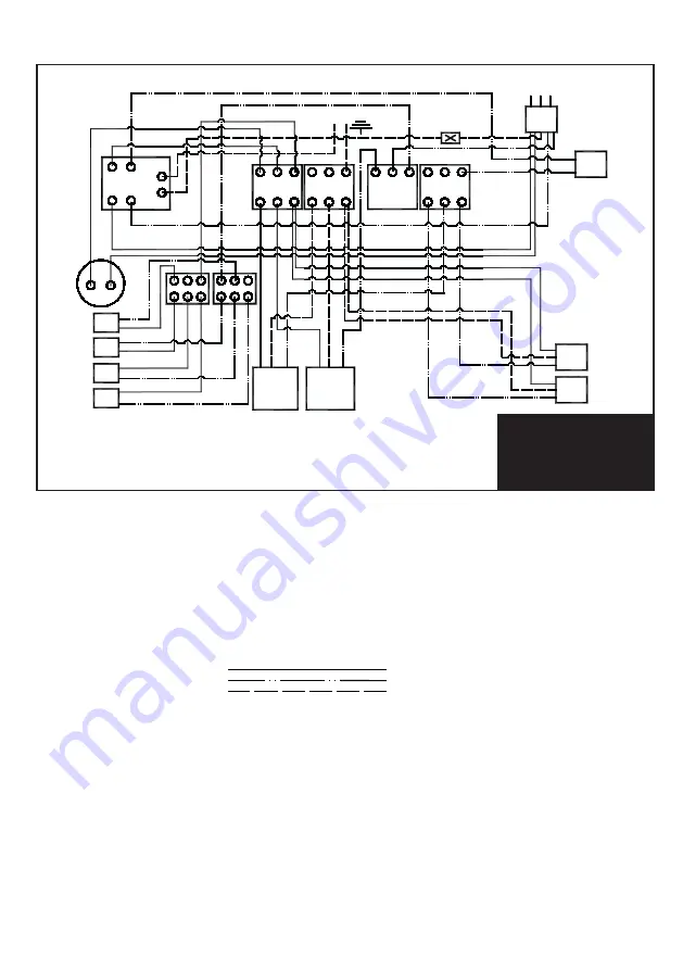
VTS250 / 250D
3
3
10
11
9
13
4
1
Connector
Earth to case
12
2
8
7
6
5
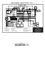
1 - Power in
2 - Pressure switch
3 - Cooling fans
4 - Thermal trip
5,6,7,8,14 & 15 Connection blocks
9 - Solenoid
10 - Motor
11 - Aftercooler fan
12 - Thermal fan switch
13 - Timer box
Note! Timer box only used
on Dryer models
NOTE!
The cooling fans
remain live even with
the power switch in
the “OFF” position
K
- Live
- Neutral
- Earth
K
KEY:
Wiring Diagrams - SINGLE PHASE - VTS
cont’d
3
3
14
15
Summary of Contents for VT150
Page 39: ...37 NOTES ...

