background image

A351, A355

PNEUMATIC TOOL

www.BAND-IT-IDEX.com

Document # P35087 Rev. I

© Copyright

BAND-IT-IDEX, Inc. 2021

All rights reserved

Page 12 of 19 

BAND-IT-IDEX, Inc.
A Unit of IDEX Corporation
4799 Dahlia Street
Denver, CO 80216-3070 USA
P: 1-800-525-0758
F: 1-800-624-3925

Operating 
Manual

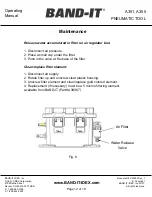
Release water accumulated in filter on air regulator box:

1. Disconnect air pressure.
2. Place a small cup under the filter.
3. Push in the valve at the base of the filter.

Clean/replace filter element:

1. Disconnect air supply
2. Rotate filter up and unscrew clear plastic housing.
3. Unscrew filter element and clean/replace gold colored element.
4. Replacement (if necessary) must be a 5 micron filtering element, 
available from BAND-IT (Part# A39987)

Air Filter

Maintenance

Water Release

Valve

Fig. 8

Summary of Contents for A35199

Page 1: ...Inc 2021 All rights reserved Page 1 of 19 BAND IT IDEX Inc A Unit of IDEX Corporation 4799 Dahlia Street Denver CO 80216 3070 USA P 1 800 525 0758 F 1 800 624 3925 Operating Manual A35199 A35599 Pneum...

Page 2: ...enver CO 80216 3070 USA P 1 800 525 0758 F 1 800 624 3925 Operating Manual Page Description Page Safety Guidelines 3 Overview Air Regulator Tool Body 4 6 Air Requirement 7 Initial Tool Set up 8 Operat...

Page 3: ...is tool applying stainless steel clamps and removing scrap clamp tail Clamp tensioning can be immediately stopped by releasing the tool trigger system When applying clamps care should be taken to ensu...

Page 4: ...poration 4799 Dahlia Street Denver CO 80216 3070 USA P 1 800 525 0758 F 1 800 624 3925 Operating Manual Precision Regulator Inside Under Clear Cover Overview Air Regulator Air Supply Inlet Mounting Br...

Page 5: ...er CO 80216 3070 USA P 1 800 525 0758 F 1 800 624 3925 Operating Manual Overview Bench Top Mounting Hole Pattern for Air Regulator Box backet Air Regulator Box Mounting In a permanent installation air...

Page 6: ...Operating Manual Important Before disassembling tool be sure to shut off air supply on the Air Regulator Module Overview Tool Body Actuator Button Red Reset Button Tension release Cut off Timing Adju...

Page 7: ...r Module includes a filter to meet these requirements For proper tool performance the air requirements at the inlet to the BAND IT Air Regulator Module must be Item Min Max Inlet Supply Pressure PSI 1...

Page 8: ...o achieve the correct psi Turn Clockwise to increase pressure counterclockwise to reduce air pressure The following set up is for reference only Micro 1 8 inch band 23 psi 80 pound pull Standard inch...

Page 9: ...eways or in any other direction when band tail is under tension or during cut off Doing so may damage clamp and or tool 3 The Pneumatic tool will automatically cut the band once the desired tension ha...

Page 10: ...be used part number E1000 For calibration procedure see Page 16 17 Calibration with device will ensure proper tension setting 3 A35199 pneumatic tool used only on 0 240 wide BAND IT Tie Dex Standard...

Page 11: ...ng calibration device must be used part number E1000 For calibration procedure see Page 16 17 Calibration with device will ensure proper tension setting 3 A35599 pneumatic tool used only on 0 120 wide...

Page 12: ...se water accumulated in filter on air regulator box 1 Disconnect air pressure 2 Place a small cup under the filter 3 Push in the valve at the base of the filter Clean replace filter element 1 Disconne...

Page 13: ...not alter factory setting unless necessary 2 A small copper screw found on the back of the tool handle above the reset button adjusts the cut off timing Fig 8 3 Using a small standard screwdriver tur...

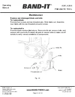
Page 14: ...ating Manual Replace worn damaged blade and knife To replace blade Remove four screws and two threaded pins Slide blade out Assemble new blade with the two threaded pins and screws To replace knife Re...

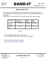
Page 15: ...maintenance including regular cleaning and lubrication will reduce the replacement frequency of these parts To maximize life use synthetic gel lubricant containing Teflon apply sparingly Replacement P...

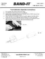
Page 16: ...tools outside their tension range 2 Cut off switch must be turned off prior to calibration 3 Attach proper tool adapter Table 3 to Calibration Device E1000 using screws and hex key provided as shown...

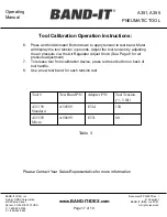
Page 17: ...dapter P N Tool Tension 5 lbf A35199 Standard A50599 E514 150 A35599 Micro A50699 E531 80 Table 3 6 Press and hold Actuator Button down to apply tension to test band Meter will display the tool tensio...

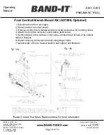
Page 18: ...2 Mount bracket to tool as shown 3 Remove air block from handle and store using second set of mounting holes 4 Attach foot control connector using button head screw 5 Mount bracket to top surface of t...

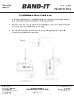
Page 19: ...3925 Operating Manual 1 If the use of a tool balancer is desired install tool balancer hook included with the tool set balancer to approximately 2 5 lbs balance weight 2 Balancer hook can be used with...

Reviews: