– Must be performed by a technician –
– Must be performed by a technician –
118
8B. Service
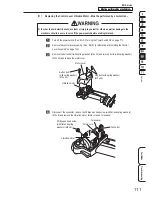
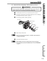
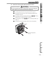
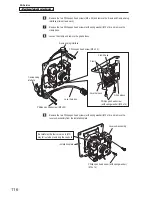
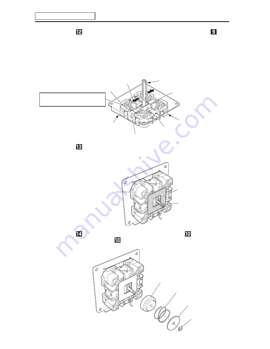
Attach the new lever sub-assembly to the installation plate by performing the step
procedure in reverse.
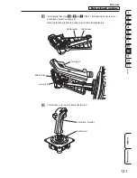
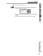
At this time attach the new lever sub-assembly so that the screw holes in the shaft of the
new lever sub-assembly face the folded-back portion of the installation plate (the direction of
the arrows), and the analog interface installation holes (without fixture) and positions where
fixtures are mounted are as shown in the figure below.
Installation plate
New lever sub-assembly
Folded-back portion
of the installation plate
(Screen side)
Analog interface installation hole (with fixture)
Analog interface installation hole (without fixture)
Analog interface
installation hole (without fixture)
Screw hole in the shaft
Analog interface installation
hole (with fixture)
Make sure that the four corner nuts (M5)
are properly inserted before assembly.
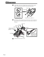
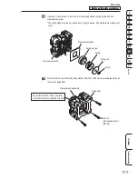
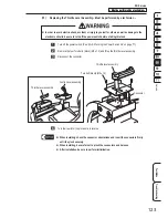
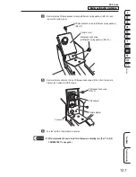
Apply silicon grease (Shin-Etsu Chemical Co., Ltd G-40M or equivalent product) to the
stainless steel plate and shaft portion of the new lever sub-assembly.
New lever sub-assembly
Stainless steel plate
(Silicon grease applied)
Shaft
(Silicon grease applied)
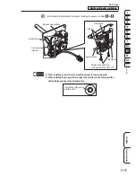
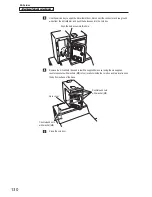
Install the spring stopper, spring and spring end removed in step
by reversing the
procedure in step
and secure them with the E-ring.
Spring stopper
Spring
Spring end
E-ring

