– Must be performed by a technician –
– Must be performed by a technician –
94
8B. Service
z
z
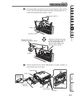
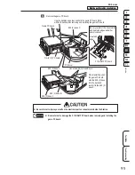
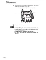
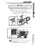
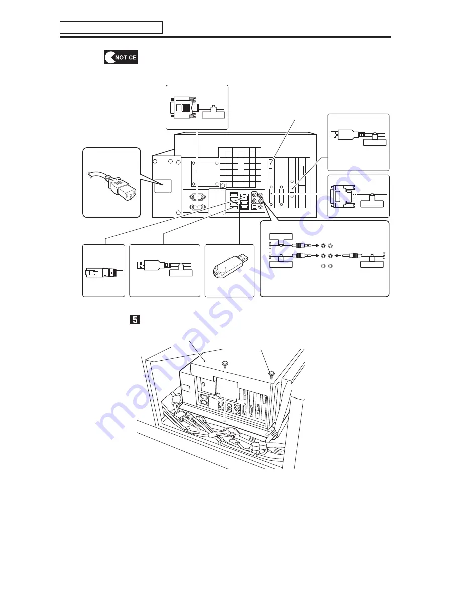
When installing, follow the indications on the game PC board and connect the
connectors correctly.
Yellow-green
1
3
Orange
Black
2
* Do not mix up with the JV I/O.
* The connection port and connector colors do not match.
Check the connector tag numbers and connect to the
connection ports with matching numbers.
* Do not mix up with the
USB sound amplifier.
SERIAL 1
JV I/O
USB 4
AUDIO 1
AUDIO 2
AUDIO 3
VIDEO
1
Power supply
(power supply convertor
cable)
No connection
JV I/O
(milky white USB cable)
Projector video
(Connect to VIDEO 1)
Projector communication
Camera module
(black USB cable)
Communication
(LAN cable)
(Connect to AC inlet of
the power supply)
USB dongle
Audio (ø3.5 stereo cable)
(Connect to USB port
No. 3.)
(Connect to SERIAL 1)
(Connect to JVI/O)
(Connect to LAN)
(Connect to USB 4)
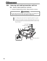
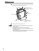
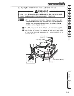
Remove the two Phillips pan head screws (with flat and spring washers) (M5 x 12).
Game PC board
Phillips pan head screws
(with flat and spring washers) (M5 x 12)

