INSTALLATION
MANUAL
MODEL 773 SERIES
REINFORCED CRASH ARM
B&B ARMR: A Division of B&B Roadway and Security Solutions
Page 24 of 38
0773-9001 Rev D
B&B ARMR reserves the right to change any information concerning product or specification without notice or obligation.
3.3.8.
Step 8 – Final Assembly
3.3.8.1.
Limit Switch Alignment
3.3.8.1.1.
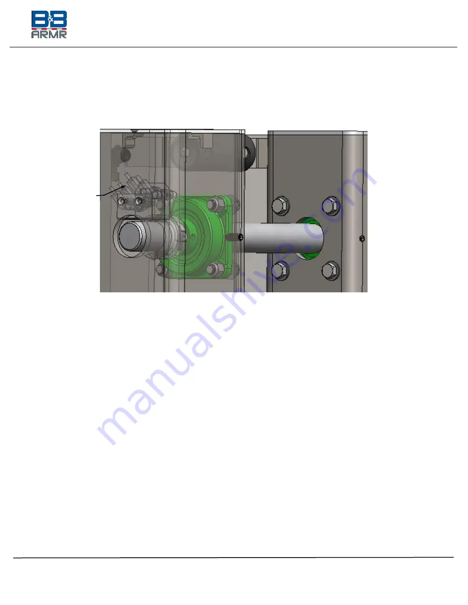
The limit switch should be installed within the drive stanchion. The switch
is meant to attach to the hinge pin and contains two (2) flags that interact
with four (4) sensors.
See Figure 16 - Limit Switch Sensor Pack
Figure 16 - Limit Switch Sensor Pack
Sensor Pack
inside of Drive
Stanchion


