232D4SS84502 Manual
Appendix B
B-5
B&B Electronics Mfg Co – 707 Dayton Rd - PO Box 1040 - Ottawa IL 61350 - Ph 815-433-5100 - Fax 815-433-5104
B&B Electronics Ltd – Westlink Comm. Pk – Oranmore, Galway, Ireland – Ph +353 91-792444 – Fax +353 91-792445
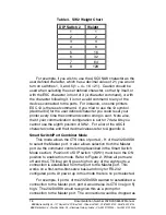
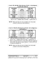
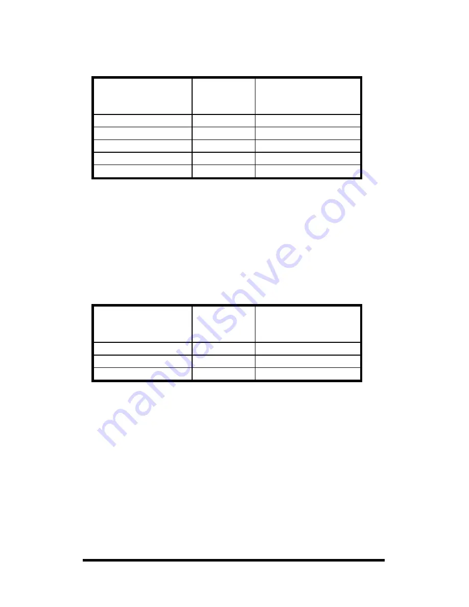
Chart 9. RS-422/485 4-Wire Device to Port (A - H) Configured
as an RS-422 /485 Port.
RS-422/485
4-Wire
Device
Signal
Direction
232D4SS8
Ports A - H
DB25 Connector
TD (A)*
----------->
17 - RD (A)
TD (B)*
----------->
16 - RD (B)
Signal Ground
<---------->
7 - SG
RD (A)*
<-----------
15 - TD (A)
RD (B)*
<-----------
14 - TD (B)
* If the device being connected uses "+" and "-" in place of "B"
and "A", the "+" replaces the "B" and the "-" replaces the "A".
NOTE:
Make sure the port's set-up jumpers are in the proper
position for four-wire communications.
Chart 10. RS-485 2-Wire Device to Port (A - H) Configured as
an RS-485 Port.
RS-485
2-Wire
Device
Signal
Direction
232D4SS8
Ports A - H
DB25 Connector
Data (A)*
<---------->
15 - TD (A)
Data (B)*
<---------->
14 -TD (B)
Signal Ground
<---------->
7 - SG
•
If the device being connected uses "+" and "-" in place of "B"
and "A", the "+" replaces the "B" and the "-" replaces the "A".
•
Place a jumper between the TD (A) and the RD (A) to make the
Data (A) line. Also place a jumper between TD (B) and RD (B)
to make the Data (B) line.
NOTE:
Make sure the port's set-up jumpers are in the proper
position for two-wire communications.

