8
Chapter 2
Documentation Number: ESP902-2303 Manual
B&B Electronics Mfg Co Inc – 707 Dayton Rd - PO Box 1040 - Ottawa IL 61350 - Ph 815-433-5100 - Fax 815-433-5104
B&B Electronics Ltd – Westlink Commercial Park – Oranmore, Galway, Ireland – Ph +353 91-792444 – Fax +353 91-792445
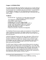
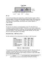
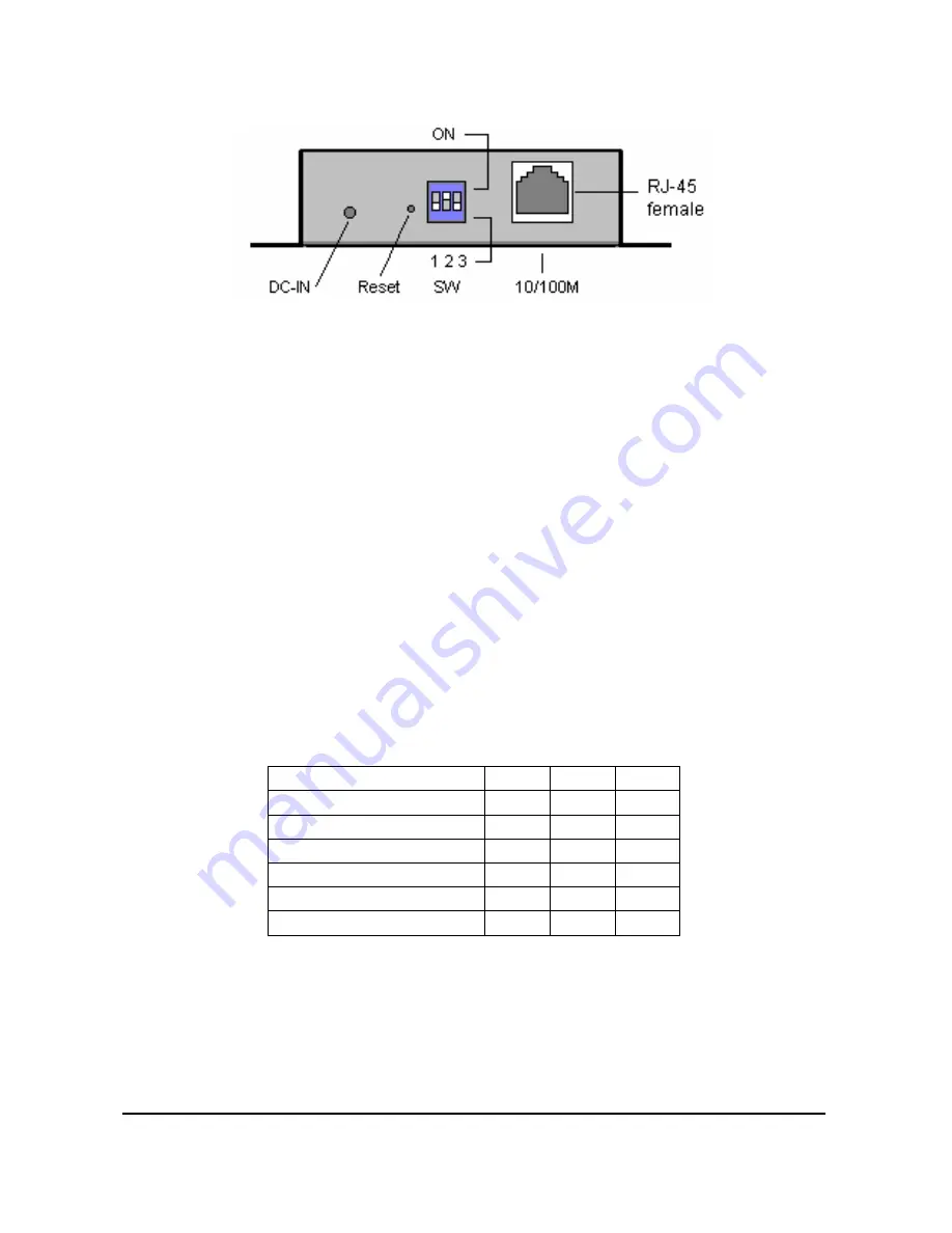
Top View
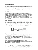
DC –In
Connect the included power supply here, and then plug the supply in. When
power is applied, the Red power light will illuminate. The tip of the power plug
is positive, sleeve is negative. The standard 12VDC/500mA power supply for
US shipment is 120VAC/60Hz, for Europe or UK it will be 230VAC or
240VAC/50Hz
.
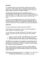
Reset Button
Resets the unit similar to removing/applying power. The Reset Button is
recessed to avoid accidental operation. To reset the unit, insert a small plastic
tool, press lightly and hold for 3 seconds. The Link and Ready lights will go out
and come back on. If you change the Mode Switch settings, you can press
Reset to reboot and read the new settings.
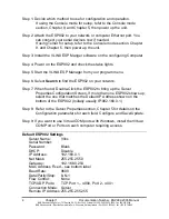
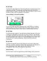
Mode Switches – ESP Server Port 1
Set the switches for the mode desired, then apply or cycle the power.
Mode SW1
SW2
SW3
RS-485 Operation
OFF OFF OFF
RS-422 Operation
ON
OFF OFF
RS-232 Operation
OFF ON
OFF
Default ON
OFF
ON
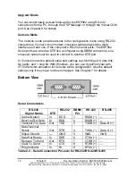
Upgrade Firmware
OFF ON
ON
Console
Menu
ON ON ON
Table 2.2 – Mode Switches
The switches set the Multi-Interface serial port to RS-485, RS-422 or RS-232
operation. They also select the Server Console mode for Configuration,
Upgrade mode for new firmware downloading or Default to reset the ESP902
to the original default settings.

