Product Introduction
Manual Documentation Number: ZXTx-IO-x-0712m
7
2.3.2 Modbus I/O Mode
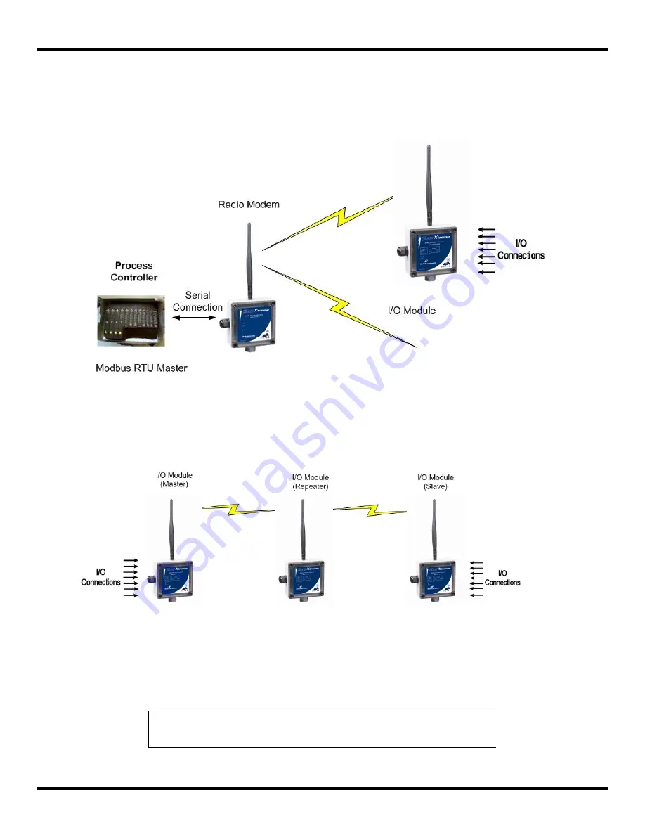
In Modbus mode, the Zlinx Xtreme I/O modules shall be configured as Modbus Slaves and can be controlled and monitored by
a Modbus RTU Master (such as a PLC, SCADA, HMI, etc). A serial radio modem acts as a data pipe & has to be connected to
the Modbus master through its serial port. Up to 247 wireless I/O modules can be remotely monitored and controlled by the
Modbus master. The I/O signals appear in the Modbus register map resident in the I/O module memory that can be accessed
by the master through the radio modem. Refer to Appendix
– D for information about the Modbus register mapping.
Figure 2-2
Modbus I/O Mode
In Modbus I/O mode, up to 247 Zlinx I/O modules can be connected to a Modbus RTU master through a Radio Modem.
Modules of both Zlinx Xtreme (outdoor) and Zlinx Gen II (indoor) types can be mixed and matched as long as their frequency
rating is the same.
2.3.3 Repeater Mode
Figure 2-3
I/O Module as a Repeater
When a Zlinx Xtreme I/O Module is configured as a repeater, it relays data from a Modbus modem or an I/O Module and
extends the range of communication. In a Peer-to-Peer System, a repeater unit can be placed between the Master and the
Slave IO modules.
Only 900 MHz radios support the repeater functionality.
NOTE:
Placing a repeater in a system will introduce an additional delay of 4ms. Each
repeater introduced in a system will cut the data bandwidth to half.
Summary of Contents for ZXT24-IO-222R2
Page 6: ......


