Hardware
Manual Documentation Number: ZXTx-IO-x-0712m
19
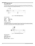
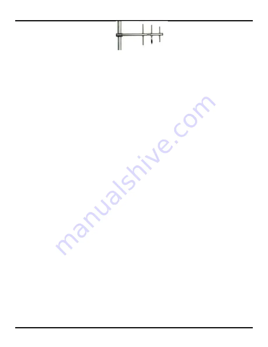
Figure 3-12
Representative Yagi Antenna
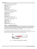
YS8963
– High Gain Yagi (900 MHz) -
For Use With: ZXT9-RM (900 MHz)
Impedance: 50 Ω
Connector: N Female
VSWR
– 1.5:1(in band)
Gain
– 6 dBi
Polarization
– Vertical
Length
– 16.8 in
Mounting Brackets
– Included
YS8966
– High Gain Yagi (900 MHz) -
For Use With: ZXT9-RM (900 MHz)
Impedance: 50 Ω
Connector: N Female
VSWR
– 1.5:1(in band)
Gain
– 9 dBi
Polarization
– Vertical
Length
– 27.8 in
Mounting Brackets
– Included
YS89612
– High Gain Yagi (900 MHz) -
For Use With: ZXT9-RM (900 MHz)
Impedance: 50 Ω
Connector: N Female
VSWR
– 1.5:1(in band)
Gain
– 11 dBi
Polarization
– Vertical
Length
– 49 in
Mounting Brackets
– Included
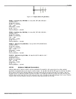
YS24008
– High Gain Yagi (2.4 GHz) -
For Use With: ZXT24-RM (2.4 GHz)
Impedanc
e: 50 Ω
Connector: N Female
VSWR
– 1.5:1(in band)
Gain
– 12.5 dBi
Polarization
– Vertical
Length
– 18 in
Mounting Brackets
– Included
3.5.5.3
Antenna Cables& Connectors
Antenna cables and connectors must be used when extending the standard or high gain antenna for outdoor antenna
applications. Appropriate cable and connector must be chosen. It is important to know that RF signal is lost across the cables
and connectors and hence for better performance, the cable length and connectors must be kept to a minimum. Also it is
important to select a cable that matches the radio‟s impedance. An impedance mismatch will cause the radio link to become
inefficient and could damage the radio. Selecting the incorrect cable could also cause significant signal loss. A rule of thumb is
for every 3 dB of loss, your system will lose one half the output power emitted from the radio.
Summary of Contents for ZXT24-IO-222R2
Page 6: ......


