Configuration & Operation
50
Manual Documentation Number: ZXTx-IO-x-0712m
6.3 Diagnostics and Testing
Most problems are related to incorrect configuration, or radio path problems. Before performing final installation of the Zlinx
Xtreme I/O modules, bench test the functionality first. If it does not work properly in this test, it will not work properly installed.
If problems are found, check wiring and software configurations.
If the bench-test is successful, and problems are experienced after installation, check the radio path.
6.3.1 Testing Modbus Mode Operation
Using a Modbus radio modem, a PC and Modbus simulation software (e.g. Modscan) you can test the link and hardware, and
investigate the operation of the Zlinx Xtreme I/O. Modscan is a Windows application that simulates a Modbus Master node.
You can read from and write to memory locations on the Zlinx Xtreme I/O. Modscan is available as a fully functional time-
limited demo from
www.win-tech.com
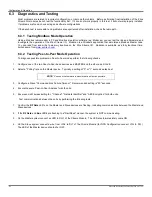
6.3.2 Testing Peer-to-Peer Mode Operation
To diagnose possible problems in Peer-to-Peer mode perform the following checks:
1. Configure one of the two Peer-to-Peer base devices as a MASTER and the other as a SLAVE.
2. Select a "Polling" rate on the Master device. Typically a setting of "0" or "1" seconds works best.
NOTE:
“0” causes the firmware to transfer data as fast as possible.
3. Configure a Slave "Communications Failure Timeout". Recommended setting is "20" seconds.
4. Ensure the same Peer
–to-Peer Address for both units.
5.
Ensure same Wireless setting for: "Channel", "Network Identifier" and “AES Encryption” for both units.
Test communications between the units by performing the following tests.
1. Confirm the
RF Data
LED‟s on the Master and Slave devices are flashing, indicating communications between the Master and
Slave devices.
2. If the
RF Data
and
Bus
LED's are flashing in a "Rail-Road" manner, the system is NOT communicating.
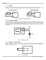
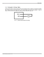
3. On the Master system connect an LED to DO-1 of the Xtreme Module. The LED should immediately come ON.
4. On the Slave system connect a wire from VIN+ to DI-1 of the Xtreme Module (for NPN Configuration connect VIN- to DI-1).
The LED of the Master device should shut OFF.
Summary of Contents for ZXT24-IO-222R2
Page 6: ......

