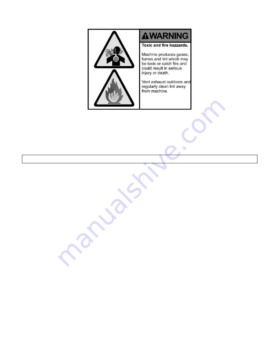
Figure 3.11: DE Series - Proper Exhaust is critical for safety!
be blocked. Blocking the air inlets prevents proper combustion, and will yield poor results, and
possibly harmful combustion byproducts. See recommended exhaust style in Figure 3.12 on page
21.
Important: Do not interrupt the flow of make-up air or the exhaust!
Use the shortest possible path with the fewest number of bends to connect to the outlet ductwork.
Measured backpressure should not exceed 0.3 inches of water column pressure for reliable ignition
and best results.
Don’t guess, measure!
Note: Check for proper exhaust fan rotation direction before placing the equipment into ser-
vice. If the rotation is incorrect, remove power from the machine and exchange any two incom-
ing power leads.
Note: Avoid locating the exhaust next to the fresh air supply intake.
Note: Avoid the use of ”booster fans”.
3.7
Plumbing Requirements
The DE series dryer can be equipped with an optional fire suppression system to reduce the risk of
fire in your dryer. If so equipped, connect the water supply to the 3/4” GHT connection, located
on the upper right rear of the machine as labeled.
If fire suppression activates, the blower will stop, the cylinder will rotate in the forward direction,
and the emitters will lightly mist the goods until the temperature drops to a safe level.
To avoid fires, keep the equipment clean, as detailed elsewhere in this manual, and always pro-
gram cool down time. No cool down time, or stopping the machine before the cycle has completed
can cause fires, as spontaneous combustion can occur in the drying cylinder.
20
Summary of Contents for DE Series
Page 1: ...Dryer DE Series Installation and Operation Manual March 17 2014 Revision 1 7 ...
Page 5: ...Figure 1 1 DE Product Family 2 ...
Page 12: ...Figure 3 1 DE Gas General Specifications 9 ...
Page 13: ...Figure 3 2 DE 30 Utility Connections 10 ...
Page 14: ...Figure 3 3 DE 50 75 Utility Connections 11 ...
Page 15: ...Figure 3 4 DE 120 Utility Connections 12 ...
Page 16: ...Figure 3 5 DE 170 Utility Connections 13 ...
Page 25: ...Figure 3 14 DE Series Bulkhead Installation Details 22 ...
Page 33: ...Figure 5 1 Simplified Call for Heat Path 30 ...
Page 34: ...Figure 5 2 Detailed Call for Heat Path 31 ...
Page 35: ...Figure 5 3 Call for Heat Path Schematic Figure 5 4 Mechanical Timer Start Path 32 ...


