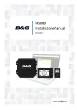
background image

ENGLISH

H5000

Installation Manual

www.bandg.com

Summary of Contents for H5000 Pilot

Page 1: ...ENGLISH H5000 Installation Manual www bandg com ...

Page 2: ...ruction manuals user guides and other information relating to the product Documentation may be translated to or has been translated from another language Translation In the event of any conflict between any Translation of the Documentation the English language version of the Documentation will be the official version of the Documentation This manual represents the product as at the time of printin...

Page 3: ...east basic knowledge of DC electrical systems and of working with power tools with materials such as fiberglass and wood An understanding of basic navigation nautical terminology and practices may be helpful in correct configuration of the product Warning It is your sole responsibility to install and use the instrument and transducer s in a manner that will not cause accidents personal injury or p...

Page 4: ...conventional navigation procedures and precautions All necessary precautions should be taken to ensure that the yacht is not placed into danger The Pilot is an aid to steering the vessel It is the user s responsibility to ensure safe control and movement of the vessel at all times Caution Electrical Supply This equipment is designed for use with a power supply source of 12 V DC The application of ...

Page 5: ... Network power supply 19 H5000 Central Processor Unit CPU 20 Status LEDs 21 CPU Installation 25 H5000 Central Processor wiring 26 Power supply 26 Masthead Unit 26 Analog input 3 4 27 Analog input 1 2 27 Pulse Paddlewheel Speed 27 Man Overboard Button input 28 Digital output Alarm 28 NMEA 0183 Channel 2 29 NMEA 0183 Channel 1 29 Network NMEA 2000 compatible 29 USB update port 30 Reset button 30 Eth...

Page 6: ...iring 43 Power 43 Drive 44 Engage Clutch 44 Alarm 45 NMEA 0183 45 Rudder 45 Remote 46 Simnet Network 46 Turning on for the first time 47 H5000 Pilot Controller 49 Commissioning 49 Dockside 57 Maintenance 57 General maintenance 58 Software upgrade 58 H5000 CPU 59 H5000 Pilot Computer Pilot Controller 59 Graphic Display 60 Race display 60 Analog Serial expansion module 60 Navico NMEA 2000 devices 61...

Page 7: ...s Proven in the world s most testing environments B G offers the most accurate and reliable systems used by blue water cruisers single handed racers and record breakers alike firmly establishing ourselves as one of the leading innovators of the most highly advanced marine electronics B G is renowned for tried and trusted solutions and is ever evolving to offer the best technology to the customer A...

Page 8: ...port and specific sailing features like wind correction for heel trim angle and true wind correction improving the data displayed to the user and guiding the autopilot It also simplifies seemingly complex calibrations through AutoCal calibration routines The H5000 CPU delivers enhanced HV display control letting you alternate the displays between two variables for more efficient display use and pr...

Page 9: ... 8 9 12 10 11 1 18 17 T T 13 19 16 15 14 12V PILOT 20 WIFI 1 No Description No Description 1 213 Masthead unit 11 3D Motion sensor 2 HV Display 12 Alarm module 3 Graphic Display 13 Wireless Access Point or Router 4 Race display 14 H5000 CPU 5 Analog display 15 Man Overboard Button 6 Zeus Touch 16 H5000 Pilot Computer 7 H5000 Pilot Controller 17 Rudder Feedback Unit 8 Heading sensor 18 Hydraulic Ra...

Page 10: ...Motion sensor 2 HV Display 17 Alarm module 3 Graphic Display 18 H5000 CPU 4 Race Display 19 Man Overboard Button 5 Analogue display 20 Analog module 6 Zeus Touch 21 Analog module 7 Zeus 22 Analog sensor 8 H5000 Pilot Controller 23 H5000 Pilot Computer 9 Analog module 24 Rudder Feedback Unit 10 Analog module 25 Hydraulic ram 11 Mast rotation sensor 26 Deckman via serial port 12 Serial Expansion Mod...

Page 11: ...PT 12V No Description No Description 1 Masthead unit 7 DST800 combined Speed Depth Temperature sensor 2 Graphic Display 8 H5000 Pilot Computer 3 H5000 Pilot Controller 9 Rudder Feedback Unit 4 GPS antenna 10 Hydraulic Ram 5 Micro C CAN bus backbone 11 Compass 6 H5000 CPU T Micro C Terminator 12V 12 Volt DC power ...

Page 12: ...ast and anti reflective and are viewable in direct sunlight but for best results install the display out of direct sunlight The chosen location should have minimal glare from windows or bright objects The enclosure that the display is mounted in should be dry and well ventilated The ventilation of the space behind the unit should be enough to prevent excessive heat build up as a combined result of...

Page 13: ... that there are no hidden electrical wires or other parts behind the panel Do not mount any part where it can be used as a hand hold where it might be submerged or where it will interfere with the operation launching or retrieving of the boat Leave sufficient clearance space to connect all relevant cables For overall width and height requirements please see the dimensions section and mounting temp...

Page 14: ...inator can be one of the following A Micro C Terminator blank plug A 508 model wind transducer where the mast cable is one end of the backbone Planning and installing a network backbone The network backbone needs to run between the locations of all products you want to install typically in a bow to stern layout and be no further than 6 m from a device to be connected Choose from the following comp...

Page 15: ...service loops Don t run cables in a way that allows water to flow down into the connectors Do tie wrap all cables to keep them secure Don t route the data cables in areas adjacent to radar transmitter or large current carrying cables If cables are shortened lengthened or re terminated do insulate and protect all wiring connections Do leave room at the back to install and remove cables Warning Befo...

Page 16: ... length of the Micro C network backbone is 100 meters For larger systems a network bridge should be considered or use Mini C cable for the network backbone which would allow a maximum of 200 meters Backbone length is calculated by adding cable lengths a b and c as shown below Note Cable lengths a c should not exceed 6 meters 1 1 1 1 1 2 2 2 2 3 4 T T a c b x No Description No Description 1 Network...

Page 17: ...ork adaptor can be used Note When using a network bridge it is important that both networks are powered and terminated as per H5000 network guidelines 12V 3 1 2 T T T 12V 12V T PILOT No Description No Description 1 Micro C CAN bus backbone 1 3 3rd party network bridge 2 Micro C CAN bus backbone 2 T Micro C Terminator 12V 12 Volt DC power supply ...

Page 18: ...e If joining to an existing Micro C CAN bus backbone or similar CAN bus network that already has its own power supply do not make another power connection Note Do not connect the Micro C CAN bus power cable to the same battery as the start batteries autopilot computer radar thruster or other high current devices The drawing below demonstrates a typical small network 12V 1 T T 5 2 3 4 6 PT 12V 12V ...

Page 19: ...nit CPU H5000 Installation H5000 Central Processor Unit CPU 1 2 3 4 5 6 No Description No Description 1 Grommet retaining clip 4 CPU lid with 6 x captive screws 2 10 hole cable grommet 5 CPU 3 5 hole cable grommet 6 CPU terminals 5 ...

Page 20: ...DESCRIPTION POWER No light No power Solid green Power on Solid red Voltage too high or too low NETWORK No light or not flashing No data being received or transmitted Flashing green Data being transmitted Solid red Network not in use or hardware error USB No light Default state when not in use Flashing green Software upgrade in progress Solid green Software upgrade successful Solid red Software upg...

Page 21: ... grommet and any surface to enable easy access to cables 3 Mark the hole positions drill pilot holes and fix into position with four self tapping screws 4 To remove the lid unscrew the 6 captive lid screws anti clockwise Note The lid comes away from the CPU The 6 captive screws remain fixed to the lid 5 Remove the grommet retaining clip 6 Remove the cable grommet 7 Feed the cut cable through the c...

Page 22: ...ble grommet Ensure the grommet is orientated in the correct direction 8 Wire the terminal plug as per the wiring instructions 9 Press the cable grommet back into place ensuring there is sufficient cable for the plug to reach the correct terminal Note Do not attach the terminal plug until the cable has been fed through the cable grommet ...

Page 23: ... 23 H5000 Central Processor Unit CPU H5000 Installation 10 Replace the grommet retaining clip 11 Example of a basic CPU wired unit shown below ...

Page 24: ... Processor Unit CPU H5000 Installation 12 Before replacing the lid ensure that the grommet and retaining clip are fitted correctly The lid will then clamp everything in place Tighten the 6 captive lid screws clockwise ...

Page 25: ...tor layout No Description No Description 1 Power 12 Volts 7 NMEA 0183 Channel 2 2 Masthead unit 8 NMEA 0183 Channel 1 3 Analog Inputs 3 4 9 Network NMEA 2000 compatible 4 Analog Inputs 1 2 10 USB port 5 Pulse input 11 Reset button 6 Man Overboard and Alarm 12 Ethernet Webserver Note There is a connection diagram on the inside of the processor lid ...

Page 26: ...scription 1 Black 0 Volts 2 Orange 12 Volts 3 4 Red Wind angle phase 5 Green Wind angle phase 6 Blue Wind angle phase 7 Violet Wind speed 8 Screen if present Analog input 3 4 1 2 3 4 5 6 Color Description 1 Sensor Dependent 0 Volts 2 Sensor Dependent 12 Volts 3 Sensor Dependent 5 Volts 4 Sensor Dependent 0 5 Volts Analog 4 5 Sensor Dependent 0 5 Volts Analog 3 6 Screen ...

Page 27: ...ts 2 Sensor Dependent 12 Volts 3 Sensor Dependent 5 Volts 4 Sensor Dependent 0 5 Volts Analog 2 5 Sensor Dependent 0 5 Volts Analog 1 6 Screen Pulse Paddlewheel Speed 1 2 3 4 Color Description 1 Black 0 Volts 2 Red 5 Volts 3 Green Pulse 4 Screen Man Overboard Button input 1 2 3 4 Color Description 1 Black Send 2 Red Return 3 4 ...

Page 28: ... output Alarm 1 2 3 4 Color Description 1 2 3 Sensor Dependent Output 4 Sensor Dependent 0 Volts 1 2 3 4 12 Volts 0 Volts NMEA 0183 Channel 2 1 2 3 4 Color Description 1 Sensor Dependent TX_A 2 Sensor Dependent TX_B 3 Sensor Dependent RX_A 4 Sensor Dependent RX_B ...

Page 29: ...TX_B 3 Sensor Dependent RX_A 4 Sensor Dependent RX_B Network NMEA 2000 compatible 1 2 3 4 Color Description 1 Red 12 Volts 2 Black 0 Volts 3 White Data high ve 4 Blue Data low ve USB update port The USB port is used for software upgrades only For further information follow the software upgrade procedure in the maintenance section of this manual ...

Page 30: ...g the power A long press of the reset button whilst powering up the CPU will initiate a full factory reset Note Performing a factory reset will revert all CPU settings to their default factory settings Ethernet port Ethernet port Direct connection to a computer or WiFi router Use the Webserver to access the CPU advanced calibration set up and diagnostics Port can use standard or crossover cables ...

Page 31: ... via Ethernet Connect a computer directly to the CPU via an ethernet cable Wireless via a WiFi 1 router Connect wireless devices to the CPU via a WiFi 1 WIFI 1 12V Note To connect the WiFi 1 router to the H5000 CPU an Ethernet to RJ45 converter cable is required ...

Page 32: ...ll say Websocket Connected in the top right hand corner of the screen next to the help tab If it says Websocket Not Connected then check the CPU and router power and connections Via wireless WiFi 1 router 1 Connect device to the CPU as shown previously 2 Open web browser on the connected computer or device 3 Find the IP address of the CPU via a Graphic Display Note The CPU IP address can be found ...

Page 33: ...oles and fix into position with two self tapping screws 3 To remove the lid unscrew the two lid screws Note The lid hinges at the bottom edge of the module To close the lid you need to locate the bottom edge first 4 Cut the grommet indicated to a length that creates a tight fit for the cable to be fed Feed the cable through and wire into the module plug Ensure the cables are positioned to the left...

Page 34: ...Expansion Modules are set via the webserver interface 1 2 3 4 5 6 7 8 1 2 3 4 5 6 7 8 Connector A Connector B Analog Expansion Module Terminal Connector A Connector B 1 Screen Screen 2 12 V 12 V 3 0 V 0 V 4 5 V 5 V 5 0 5 V input 0 5 V input 6 0 5 V input 0 5 V input 7 0 5 V input 0 5 V input 8 Pulse 1 Pulse 2 Serial Expansion Module Terminal Connector A Connector B 1 Screen Screen 2 5 V 12 V 3 0 V...

Page 35: ...is an example of how to wire an Analog module with a masthead unit and paddle wheel sensor Masthead Unit 1 Screen 2 Orange 3 Black 4 5 Blue 6 Green 7 Red 8 Violet 1 2 3 4 5 6 7 8 1 2 3 4 5 6 7 8 Paddle Wheel Sensor 1 Screen 2 3 Black 4 Red 5 6 7 8 Green Masthead Unit Paddle Wheel Sensor ...

Page 36: ...nalog or Serial Expansion Module draw more than 300 mA current total then a terminal link must be placed onto both jumpers located above the network connector inside the module as shown below This bypasses the isolated power supply within the module Note Do not bypass the isolated power supply unless necessary ...

Page 37: ...0 Volts 4 5 Blue Wind Angle Phase 6 Green Wind Angle Phase 7 Red Wind Angle Phase 8 Violet Wind Speed 5 V Analog input 0 V to 5 V signal CONNECTOR A TOP TERMINALS 1 2 3 4 5 6 7 8 Color Input Channel 1 Screen 2 3 Black 0 Volts 4 Red 5 Volts 5 Sensor dependent Signal 0 V to 5 V Analog 1 6 Sensor dependent Signal 0 V to 5 V Analog 2 7 Sensor dependent Signal 0 V to 5 V Analog 3 8 7 ...

Page 38: ... dependent Signal 0 V to 5 V Analog 5 7 Sensor dependent Signal 0 V to 5 V Analog 6 8 Note 0 Volt to 5 Volt sensors can be wired into either Connector A or Connector B If you plug a 0 5 Volt analog input into connector 1 then the analog channels will be 1 2 3 if connected to connector 2 then they will be channels 4 5 6 Paddle wheel 1 2 3 4 5 6 7 8 Color Input 1 Screen 2 3 Black 0 Volts 4 Red 5 Vol...

Page 39: ... Expansion H5000 Installation Paddle wheel Sea temperature 1 2 3 4 5 6 7 8 Color Input 1 Screen 2 3 Black 0 Volts 4 Red White 5 Volts 5 Yellow Sea Temperature 6 7 8 Green Speed Note 10 K ohm resistor required between terminal 5 and 3 ...

Page 40: ...r Dependent RX_B Note A link wire may be required as shown between terminals 3 6 and 6 8 depending on the sensor Halcyon Gyro Stabilized Compass HGSC Note Fit the module jumper as previously described to bypass the isolated power supply CONNECTOR B BOTTOM TERMINALS 1 2 3 4 5 6 7 8 Color Input 1 Screen 2 Red 12 Volts 3 Black 0 Volts 4 5 Green HGSC Data out 6 Blue HGSC Data out 7 White HGSC Data in ...

Page 41: ...the module vertically Ensure that there is at least 100 mm clearance between the connector and grommet and any surface to enable easy access to cables 2 Mark the hole positions drill pilot holes and fix into position with two self tapping screws Note If installing a 3D Motion Sensor ensure that it is installed vertically and facing forwards towards the bow of the boat as shown below 9 ...

Page 42: ...rom functioning properly Wiring Access the terminals by removing the 6 captive screws in the H5000 Pilot Computer lid Follow the same method as described for the CPU 2 3 4 7 DRIVE 30 A FUSE POLARITY LEDS DRIVE ENGAGE SUPPLY NMEA0183 ALARM SCREEN TERMINATION REMOTE SIMNET RUDDER 5 6 8 9 10 11 1 Connector layout No Description No Description 1 Polarity LEDs 7 NMEA 0183 2 30 Amp fuse 8 Alarm 3 Power ...

Page 43: ... Description 1 Drive Dependant Motor Solenoid 1 2 Drive Dependant Motor Solenoid 2 3 Drive Dependant Solenoid ground Note The drive cable is hard wired directly to the drive terminal on the PCB Reversing drive Hydraulic drives and rotary drives need connection to the Engage terminal for clutch operation MOTOR SOL 1 MOTOR SOL 2 SOL GND DRIVE ENGAGE CMD RET H5000 Pilot Rotary drive CLUTCH MOTOR Hydr...

Page 44: ...DRIVE H5000 Pilot SOL GND SOL 1 SOL 1 Note For solenoids with higher voltage 110 220 V AC or DC use external relays solid state relays Engage Clutch 1 2 Color Description 1 Drive Dependant Engage Command 2 Drive Dependant Engage Return Alarm 1 2 Color Description 1 Alarm Dependant Input 2 Alarm Dependant Return ...

Page 45: ...endent RX_B 2 Sensor Dependent RX_A 3 Sensor Dependent TX_B 4 Sensor Dependent TX_A Rudder 1 2 Color Description 1 Brown Frequency 2 Grey Frequency Remote 1 2 3 4 Color Description 1 Remote Dependant Lamp 2 Remote Dependant Starboard 3 Remote Dependant Port 4 Remote Dependant Ground ...

Page 46: ...tallation instructions The first time the autopilot system is started and after a factory reset you will need to follow the setup and commissioning procedures as described Note Some important points regarding the installation settings When the autopilot is delivered from factory and ANY TIME AFTER AN AUTOPILOT RESET HAS BEEN PERFORMED the installation settings are all reset to factory preset defau...

Page 47: ...ourse 10º Starboard Activates Non Follow Up NFU mode when in Standby mode 3 1º COURSE CONTROL STARBOARD Change target course 1º Starboard Activates Non Follow Up NFU mode when in Standby mode Enter menu 4 10º COURSE CONTROL PORT Change target course 10º Port Activates Non Follow Up NFU mode when in Standby mode 5 1º COURSE CONTROL PORT Change target course 1º Port Activates Non Follow Up NFU mode ...

Page 48: ... Connectors The H5000 Pilot Controller is equipped with 1 Micro C flying lead Network The H5000 Pilot Controller can be connected at any point on the network Note The H5000 Pilot Controller is only compatible with the B G H5000 Pilot ...

Page 49: ...stallation settings must be performed as part of the commissioning of the autopilot system Failure to do so correctly may prohibit the autopilot from functioning properly The Installation menu can only be accessed in Standby mode Dockside The dockside procedures are initiated from the commissioning dialog via the H5000 Pilot Controller Boat length Set the boat length of the vessel Drive voltage V ...

Page 50: ...ifferent from the angle displayed correct the reading with the Up Down keys 3 Confirm Rudder feedback calibration to starboard by pressing 1º Starboard key Max port The Max starboard angle is the angle read by the rudder feedback unit before any adjustment is made 1 Manually move the helm to port until the rudder stops at port lock hard over Press 1º Starboard key to confirm 2 Adjust the displayed...

Page 51: ...Drive engage has the following settings Auto and Clutch Auto This setting is implemented for future use Always use the Clutch default setting Clutch This is the default setting and it allows you to steer the boat from the helm when in Standby mode A clutch will be engaged on the drive unit locking out the steering when the autopliot is engaged Motor output The Motor output displayed as a percentag...

Page 52: ...type from the available options Rudder Test Note If the boat uses power assisted steering it is important that the engine or electric motor used to enable the power assist steering be turned on prior to this test Warning Stand CLEAR of the wheel and do not attempt to take manual control of the wheel during this test Bring the rudder manually to midship position before starting the test After a few...

Page 53: ... automatically as a function of the boat type selection performed in the Dockside menu The automatic tuning process is also verifying adjusting the Rudder zero alignment made in Dockside setup Recommended speed during Auto Tune should not exceed 10 knots It should be performed in calm or moderate sea conditions For displacement boats use a speed that is approximately half the normal cruising speed...

Page 54: ...e Main menu Rudder gain Sets the rudder gain which is the ratio between the commanded angle and the heading error Too little rudder Set course Too much rudder Set course Too little Rudder gain and the autopilot fails to keep a steady course Too much Rudder gain gives unstable steering and reduces speed Low speed requires more rudder gain than high speed Counter rudder Counter Rudder is the paramet...

Page 55: ...ong side counter rudder The best way of checking the value of the Counter Rudder setting is when making turns The figures illustrate the effects of various Counter Rudder settings Counter rudder setting too low Overshoot response Counter rudder setting too high Sluggish and creeping response Correct setting of counter rudder ideal response New course New course New course ...

Page 56: ...e Response adjust Set waypoints into each navigator connected to the system and verify that the autopilot steers in Navigation mode for each Navigation source Use the Wind mode in both Apparent and True modes and engage the autopilot at different wind angles If the rudder response feels aggressive during the sea trial try to reduce the rudder speed to get smoother steering Use a higher rudder spee...

Page 57: ...important to avoid using chemical cleaners alcohols and hydrocarbons such as diesel petrol etc Always put on the weather cover when the unit is not in use Checking the keys Make sure that no keys are stuck in the down position Checking the connectors The connectors should be checked by visual inspection only Ensure that cables are connected correctly and any unused terminals are protected Software...

Page 58: ...5 Turn on power to the CPU 6 The CPU will automatically recognise the upd file and begin the upgrade process 7 To indicate the upgrade is in progress the USB LED on the top of the CPU will flash green 8 When the USB LED turns solid green stops flashing the upgrade process is complete 9 Remove the USB stick the CPU will automatically reboot Note A solid red light on the USB LED indicates the upgrad...

Page 59: ...ve upd file to a USB Stick Must be in the root folder and not a subfolder 2 Turn off power to the Graphic Display 3 Remove the service port cap on the rear of the display by unscrewing it anti clockwise using a suitable coin 4 Place USB stick into the USB port 5 Turn on power to the Graphic Display 6 The display will automatically recognise the upd file and begin the upgrade process 7 The display ...

Page 60: ... MFD or Navico Software Upgrade Tool Analog Serial expansion module To upgrade Analog Serial expansion modules to the latest software version use a MFD or the Navico Software Upgrade Tool Navico NMEA 2000 devices To upgrade NMEA 2000 devices to the latest software version use a MFD or the Navico Software Upgrade Tool ...

Page 61: ... 8 31 195 0 mm 7 68 65 5 mm 2 58 92 0 mm 7 68 196 0 mm 7 72 Weight 0 7 kg 1 6 lbs Supply voltage 12 V DC Nominal 9 16 V Power consumption 2 4 Watts 200 mA 12 V Typical Can bus power consumption 0 6 Watts 50 mA 12 V Typical NMEA 2000 equivalent 1 LEN Color Black Environmental Protection IPX4 Safe distance to com pass 0 3 m 1 0 ft 13 ...

Page 62: ...84 5 mm 7 26 Weight 0 45 kg 1 0 lbs Supply voltage 12 V DC Nominal 9 16 V Network pow ered Power consumption 1 9 Watts 160 mA 12 V Typical 2 3 Watts 190 mA 12 V Max NMEA 2000 equivalent 3 LEN Color Black Display Size 5 Diagonal 4 3 Aspect ratio Type Transmissive TFT LCD White LED back light Color 16 bit high color Resolution 480 x 272 pixels Environmental Protection IPX7 Safe distance to compass 0...

Page 63: ...mm 4 69 184 5 mm 7 26 Weight 0 45 kg 1 lbs Supply voltage 12 V DC Nominal 9 16 V Network pow ered Power consumption 0 6 Watt 50 mA 12 V Typical 1 0 Watts 86 mA 12 V Max NMEA 2000 equivalent 2 LEN Color Black Display Size 5 Diagonal Type Transflective 7 segment LCD White Red LED back light Color Monochrome Resolution 7 segment LCD Environmental Protection IPX7 Safe distance to compass 0 3 m 1 0 ft ...

Page 64: ...11 0 mm 8 31 195 0 mm 7 68 65 5 mm 2 58 92 0 mm 7 68 196 0 mm 7 72 Weight 0 7 kg 1 6 lbs Supply voltage 12 V DC Nominal 9 16 V Power consumption 0 6 Watts 50 mA 12 V Typical NMEA 2000 equivalent 1 LEN Color Black Environmental Protection IPX4 Safe distance to compass 0 3 m 1 0 ft ...

Page 65: ...t Outline Sun Cover Outline Sun Cover Outline 9 0 mm 0 35 Weight 0 18 kg 0 4 lbs Power consumption 1 2 Watt 100 mA 12 V Typical 1 6 Watts 130 mA 12 V Max NMEA 2000 equivalent 3 LEN Color Black Display Size 2 Diagonal Type LED Transflective Color Monochrome Resolution 128 x 64 pixels Environmental Protection IPX7 Safe distance to compass 0 3 m 1 0 ft ...

Page 66: ...www bandg com 988 10635 001 ...

Reviews: