Ethernet
Connect the Ethernet connector to your vessels B&G CPU Ethernet network for transfer of data to the displays.
No special setup is required for establishing an Ethernet network.
A.
Ethernet switch, display port 1-3
B.
Display power and Ethernet cable
C.
Display
A
C
Ethernet
Ethernet
B
C
D
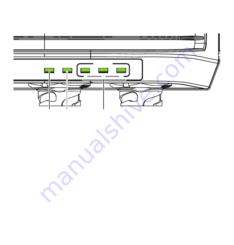
LED indicators
A.
Power (PWR)
The power indicator is lit when the unit is powered.
B.
Ethernet (ETH)
The Ethernet indicator blinks while data is transferred
between the hub and the vessels Ethernet network.
C.
Display 1-3
The display indicators blinks while data is transferred
between the hub and the connected display.
Grounding
It is recommended to ground the unit. 1.5 mm2 (16 AWG)
wire.
Connectors overview
Top connectors
Bottom connectors
ETHERNET
DISPLAY 1
DISPLAY 2
A
B
C
DISPLAY 3
GROUND
D
E
Display wiring
Ethernet and power wiring
A.
Shield
B.
Ethernet connector (RJ45)
C.
Not used, yellow
D.
+12/24 V DC, red
E.
DC negative, black
B
C
D
E
A
A
B
PWR
ETH
DISPLAY
1
2
3
C
PWR
ETH
DISPLAY
1
2
3
A
B
C
Screw M4 (max 7 mm (0.27”))
Power
The unit is designed to be powered by 12 or 24 V DC system. It is protected against reverse polarity, under voltage, and over
voltage (for a limited duration). A fuse or circuit breaker should be fitted to the positive supply. For recommended fuse rating refer
to the technical specifications.
The shield (
A
) can in most cases be insulated from all other wires. If interference is encountered from other on board electronics,
the shield can be connected to a vessel hull ground to help reduce any interference, but it is not generally required.
The yellow wire (
B
) in the power cable is is not to be used and should be insulated from all other wires.
A.
Shield
B.
Not used, yellow
C.
+12/24 V DC, red
D.
DC negative, black
E.
Switch
F.
Fuse
E
D
F
A
B
C
The unit will turn on when power is applied.
A.
Ethernet switch with a 5-pin Ethernet socket
B.
B&G CPU or Ethernet switch with a RJ45 Ethernet socket
C.
Ethernet cable plug (RJ45)
D.
Ethernet adapter cable (RJ45 to 5-pin), optional
A.
Ethernet - Power and Ethernet connection
B.
Display connector 1
C.
Display connector 2
D.
Display connector 3
E.
Ground, M4
Summary of Contents for NEMESIS
Page 1: ... 988 12791 001 NEMESIS HUB INSTALLATION GUIDE ...
Page 3: ...Dimensional drawing 151 64 mm 5 97 52 75 mm 2 08 98 61 mm 3 88 275 8 mm 10 86 187 5 mm 7 38 ...
Page 4: ...Mounting 1 2 3 ...
Page 8: ...Grounding It is recommended to ground the unit 1 5 mm2 16 AWG wire Screw M4 max 7 mm 0 27 ...


