background image

Reset device ID

Should a radar be connected to the network that has been
connected to a dual radar network in the past, it might not be
detected by the system because it might have an invalid Device ID.
With the radar connected and powered up, select the Reset Device
ID button to resolve this problem.

Ú

Note: 

This procedure must be performed with only one radar

on the network, and only applies where a network combines an
older MFD with other MFDs.

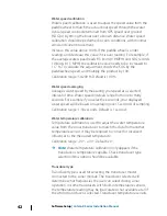
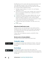
Adjust antenna height

Set the radar scanner height relative to the water surface. The Radar
uses this value to calculate the correct STC settings.

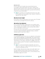
Adjust bearing alignment

This is to align the heading marker on the screen with the center
line of the vessel. This will compensate for any slight misalignment
of the scanner during installation. Any inaccuracy will be evident
when using MARPA or chart overlay.
Point the boat to be perpendicular to the very end of a breakwater
or peninsula. Adjust the bearing alignment setting, so that the
heading marker and land mass intersect.

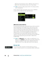
Sidelobe suppression

Occasionally false target returns can occur adjacent to strong target
returns such as large ships or container ports. This occurs because
not all of the transmitted radar energy can be focused into a single
beam by the radar antenna, a small amount energy is transmitted in
other directions. This energy is referred to as sidelobe energy and
occurs in all radar systems. The returns caused by sidelobes tend to
appear as arcs.

Ú

Note: 

This control should only be adjusted by experienced

radar users. Target loss in harbor environments may occur if this
control is not adjusted correctly.

When the radar is mounted where there are metallic objects near
the radar, sidelobe energy increases because the beam focus is
degraded. The increased sidelobe returns can be eliminated using
the Sidelobe Suppression control.

Software Setup

 | Vulcan R Series Installation Manual

45

Summary of Contents for Vulcan R

Page 1: ...VulcanRSeries Installation Manual ENGLISH www bandg com ...

Page 2: ......

Page 3: ...ning Language This statement any instruction manuals user guides and other information relating to the product Documentation may be translated to or has been translated from another language Translation In the event of any conflict between any Translation of the Documentation the English language version of the Documentation will be the official version of the Documentation This manual represents ...

Page 4: ... radio exempts de licence L exploitation est autorisée aux deux conditions suivantes 1 l appareil ne doit pas produire de brouillage et 2 l utilisateur de l appareil doit accepter tout brouillage radioélectrique subi même si le brouillage est susceptible d en compromettre le fonctionnement Warning The user is cautioned that any changes or modifications not expressly approved by the party responsib...

Page 5: ...t connection or a pay per MB type internet connection may require large data usage Your service provider may charge you based on the amount of data you transfer If you are unsure contact your service provider to confirm rates and restrictions Countries of intended use in the EU AT Austria BE Belgium BG Bulgaria CY Cyprus CZ Czech Republic DK Denmark EE Estonia FI Finland FR France DE Germany GR Gr...

Page 6: ...opyright 2012 Fishing Hot Spots FUSION Link Marine Entertainment Standard is a registered trademark of FUSION Electronics Ltd C MAP is a registered trademark of C MAP SD and microSD are trademarks or registered trademarks of SD 3C LLC in the United States other countries or both Additional mapping data Copyright 2012 NSI Inc Copyright 2012 by Richardson s Maptech Bluetooth is a registered trademar...

Page 7: ...ortant text that requires special attention from the reader is emphasized as follows Ú Note Used to draw the reader s attention to a comment or some important information Warning Used when it is necessary to warn personnel that they should proceed carefully to prevent risk of injury and or damage to equipment personnel Preface Vulcan R Series Installation Manual 7 ...

Page 8: ...8 Preface Vulcan R Series Installation Manual ...

Page 9: ... connections 24 Power Control connection 27 External alarm 27 Connecting control devices 28 NMEA 2000 backbone 30 CZone connection to NMEA 2000 31 Transducer connection 31 Radar connector 33 Software Setup 33 First time startup 33 Time and Date 33 Start line vessel configuration 34 Rotating mast compensation 35 Data source selection 36 Device list 37 Network groups 38 Diagnostics 39 Damping 39 Cal...

Page 10: ...rcury 57 Software updates and data backup 61 Accessories 63 Supported data 63 NMEA 2000 compliant PGN List 66 Technical specifications 66 All units 68 Dimensional drawings 68 5 unit dimensional drawings 68 7 unit dimensional drawings 69 9 unit dimensional drawings 69 12 unit dimensional drawings 10 Contents Vulcan R Series Installation Manual ...

Page 11: ...LISH InstallationManual bandg c om ENG LISH InstallationManual bandg c om 1 2 3 4 5 6 7 8A 8B 8C 1 Display unit 2 Panel mounting kit Gasket Mounting screws 4x 4 x 3 4 PN HD SS 3 Sun cover 4 Cable Combined power and NMEA 2000 cable 5 unit Power cable 7 9 and 12 units 5 Fuseholder and fuse 3 A ATC blade 1 Check the contents Vulcan R Series Installation Manual 11 ...

Page 12: ...ing kit 5 unit Quick Release Bracket Mounting screws 4x 10 x 3 4 PN HD SS B Bracket mounting kit 7 and 9 units U bracket plastic Mounting screws 4x 10 x 3 4 PN HD SS Bracket knobs 2x C Bracket mounting kit 12 unit U bracket metal Mounting screws 4x 10 x 3 4 PN HD SS Bracket knobs 2x 12 Check the contents Vulcan R Series Installation Manual ...

Page 13: ...ping providers in the AT5 format For a full selection of available charts visit www gofreemarine com www c map com or www navionics com The unit may be mounted to the vessel with the supplied mounting bracket or panel mounted The unit is intended for 12 V DC operation and will accept the moderate fluctuations commonly seen in DC systems Front controls 2 1 1 Touch screen 2 Power button Press and ho...

Page 14: ...ower 12 V DC supply input and NMEA 2000 7 9 and 12 units rear connections 1 2 3 4 RADAR NMEA2000 POWER SONAR 1 Radar radar Ethernet connection 2 NMEA 2000 data input output 3 Power 12 V DC supply input 4 Sonar CHIRP Broadband DownScan and SideScan imaging dependent on the transducer 14 Overview Vulcan R Series Installation Manual ...

Page 15: ...files to a chart card Doing so can damage chart information on the chart card The card reader door is opened by pulling the rubber cover open The card reader door should always be securely shut immediately after inserting or removing a card in order to prevent possible water ingress Cardreaderonthe5 unit Cardreaderonthe7 and9 units Cardreaderonthe12 unit Overview Vulcan R Series Installation Manua...

Page 16: ...s are known to impact the performance in a negative way Test the unit in its intended location to ensure satisfactory reception An external GPS source can be added to overcome poor GPS reception areas An external wireless module can be added to compatible devices to overcome poor wireless reception areas Consider access to the card reader which is located in the back of the unit Check that it is p...

Page 17: ...ccommodate the unit fitted in the bracket allows tilting of the unit and connecting cables in the back Ú Note Ensure that the chosen location has enough height to accommodate the unit fitted in the bracket allows tilting of the unit and connecting cables in the back 2 Mark the screw locations using the bracket as a template and drill pilot holes Ú Note Use fasteners suited to the mounting surface ...

Page 18: ...e unit to the desired position angle Removing the unit from the quick release bracket Pull and hold the release handle and then pull the unit from the bracket 18 Installation Vulcan R Series Installation Manual ...

Page 19: ...the screw locations using the bracket as a template and drill pilot holes Use fasteners suited to the mounting surface material If the material is too thin for self tappers reinforce it or mount the bracket with machine screws and large washers Use only 304 or 316 stainless steel fasteners 3 Screw down the bracket 4 Mount the unit to the bracket using the knobs Hand tighten only The ratchet teeth ...

Page 20: ...ery low profile and therefore fully conceal the locking tabs that keep it from being accidentally disengaged from the mounting flange To release the locking tabs gently insert a thin object between the bezel and the screen frame When the first locking tab is released and an opening is visible carefully release the remaining locking tabs and remove the bezel 20 Installation Vulcan R Series Installa...

Page 21: ...s in the screen frame Secure the bezel to the screen frame by gently pressing the bezel against the screen frame Transducer installation For transducer installation information refer to separate installation instructions included with the transducer Installation Vulcan R Series Installation Manual 21 ...

Page 22: ...ble crimp connectors or solder and heat shrink Keep joins as high as possible to minimize possibility of water immersion leave room adjacent to connectors to ease plugging and unplugging of cables Warning Before starting the installation be sure to turn electrical power off If power is left on or turned on during the installation fire electrical shock or other serious injury may occur Be sure that...

Page 23: ...e following Power into the system Red and Black wires Controlling power state of the unit Yellow wire 1 6 _ 2 3 5 4 1 Power cable 2 12 V DC positive wire red shown with fuse holder fitted 3 12 V DC negative wire black 4 Power control wire yellow 5 Vessel s 12 V DC supply 6 NMEA 2000 cable and connector Connect Red to DC using a 3 amp fuse Connect Black to DC The unit can be powered on and off usin...

Page 24: ...ernal alarm Blue wire _ 1 2 3 5 6 4 1 Power cable 2 12 V positive wire red shown with fuse holder fitted 3 12 V negative wire black 4 Power control wire yellow 5 Alarm wire blue 6 Vessel s 12 V DC supply Connect Red to DC using a 3 amp fuse Connect Black to DC The units can be powered on and off using the power button on the front of the case Power Control connection The yellow Power Control wire ...

Page 25: ...ble connector to unit 2 Positive wire red 3 Ground wire black 4 Power control wire yellow 5 Alarm wire blue Power Control to supply positive auto on Device will turn on immediately when power is applied Common the yellow wire with the red wire after the fuse Ú Note The unit cannot be powered down by power button but can be put in to standby mode The screen backlight turns off _ 1 2 4 3 5 Wiring Vu...

Page 26: ...rned on to start engines Connect the yellow wire to the accessories output of the engine key switch Ú Note Engine start batteries and house batteries should have a common ground connection _ 5 1 2 3 4 6 1 Power cable connector to unit 2 Positive wire red 3 Ground wire black 4 Power control wire yellow 5 Alarm wire blue 6 Ignition switch 26 Wiring Vulcan R Series Installation Manual ...

Page 27: ...es Individual devices can also be configured to not sound their internal buzzer but still display the alarm information For information about configuring alarms refer to the Alarms section in the Operator Manual For sirens that draw more than 1 Amp use a relay _ A B D C Buzzer _ A B D C Siren A Negative power wire black B Positive power wire red C Power control wire yellow D Alarm wire blue Connec...

Page 28: ... network information The standardized physical cables connectors for NMEA 2000 are Micro C and Mini C directly derived from the automation industries DeviceNET Micro C being the more commonly used size While most Navico products use Micro C cabling and connectors some products still use proprietary SimNet connectors which are easily made compatible with adaptor cables A network consists of a linea...

Page 29: ... 25 ft cables T connector or 4 way connector Used to connect a drop cable to the backbone Micro C power cable Connect to the backbone at a position that is central to the network load using a T connector or 4 way connector Ú Note When using a wind sensor the mast cable should be connected at one end of the backbone as the sensor is fitted with a termination resistor Ú Note Most NMEA 2000 devices c...

Page 30: ... V DC T 3 4 4 6 2 1 T 5 1 NMEA 2000 device 2 Connector to unit 3 Drop cable should not exceed 6 m 20 ft 4 Terminators 5 Backbone 6 Power cable CZone connection to NMEA 2000 When interfacing to CZone network it is recommended to use a BEP Network interface bridge to join the two network backbones together The CZone NMEA 2000 Network interface bridge isolates the power of the two networks but allows...

Page 31: ... pin connector can be plugged directly into the 9 pin port on the back of the unit For connector location refer to the embossed labeling on the back of the unit or the section Rearconnections on page 14 Ú Note The connector attached to the transducer cable is keyed and can only be inserted in one orientation Once inserted turn locking collar to secure Ú Note A 7 pin transducer cable can be connect...

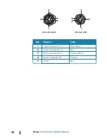
Page 32: ... 2 3 1 4 5 Cableplug male Key Purpose Color 1 Transmit positive TX Blue White 2 Transmit negative TX Blue 3 Receive positive RX Orange White 4 Receive negative RX Orange 5 Shield Bare 32 Wiring Vulcan R Series Installation Manual ...

Page 33: ... default the unit displays a setup wizard Respond to the setup wizard prompts to select some fundamental setup options You can perform further setup using the system settings option and later change settings made with the setup wizard Time and Date Configure time settings to suit vessel location along with time and date formats Start line vessel configuration In order for the start line feature to...

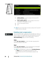
Page 34: ...Provided the mast is also fitted with a sensor to measure rotation the effect can be compensated for Open the Advanced Settings page to access the following Radar Enable Use mast rotation to ensure the radar image alignment stay correct relative to the vessel Wind Enable Use mast rotation to ensure the apparent and calculated wind heading stays correct relative to the vessel Ú Note If using H5000 ...

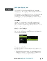
Page 35: ...ion looks for all sources connected to the device If more than one source is available for each data type selection is made from an internal priority list This option is suitable for the majority of installations Manual source selection Manual selection is generally only required where there is more than one source for the same data and the automatically selected source is not the one desired Grou...

Page 36: ... the desired source which may be corrected using the Advanced Source Selection An example of this is where twin installations with NMEA 2000 compliant engines are not programmed with unique instance numbers This means that the auto select feature cannot determine which engine is fitted on the port and which is fitted on the starboard side Ú Note The Advanced option is visible in multiple places th...

Page 37: ...ing the instance number on a 3rd party product is typically not possible Network groups The Network Groups function is used to control parameter settings either globally or in groups of units The function is used on larger vessels where several units are connected to the network By assigning several units to the same group a parameter update on one unit will have the same effect on the rest of the...

Page 38: ...termination or cable topology is incorrect Rx Overflows The unit received too many messages for its buffer before the application could read them Rx Overruns The unit contained too many messages for its buffer before the driver could read them Rx Tx Errors These two numbers increase when there are error messages and decrease when messages are received successfully These unlike the other values are...

Page 39: ... here will ONLY be applied locally to this unit Other devices on the network will not have these offsets applied External Alarm Setup The Siren Enabled option must be set in order for the unit to activate the buzzer when an alarm condition arises Its setting also determines the operation of the external alarm output Echosounder setup Make general settings from the Echosounder Settings dialog Defin...

Page 40: ...m the water surface to the bottom do the following Before setting the Structure offset measure the distance from the structure transducer to the water surface If for example the distance is 0 3 m 1 ft it will be input as plus 0 3 m 1 ft A setting of 0 zero causes the depth displayed to be the distance from the transducer to the bottom Echosounder installation Use this dialog to setup and configure...

Page 41: ...st point of the boat in the water or from the transducer to the water surface A For depth below keel Set the distance from transducer to the bottom of the keel this should be set as a negative value For example 2 0 B For depth below transducer no offset required the offset is set to 0 C For depth below surface waterline Set the distance from transducer to the surface this should be set as a positi...

Page 42: ... one to thirty seconds For example if you select five seconds your displayed water speed will be based on averaging over 5 seconds of sampling Calibration range 1 30 seconds Default is 1 second Water temperature calibration Temperature calibration is used to adjust the water temperature value from the sonar transducer to match the data from another temperature sensor It may be required to correct ...

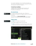
Page 43: ... feature is automatically enabled when a TotalScan or StructureScan HD transducer is plugged in before the unit has been powered on It is possible to set a Structure depth offset for the structure transducer This setting is in the Echosounder Settings dialog Radar setup Ú Note The 5 unit does not support radar Use the Radar Installation dialog to setup the radar Ú Note The installation can vary de...

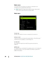
Page 44: ...del of scanner connected to the network Software version Check to make sure you have the latest software Check the latest software version available at www bandg com Serial Number This number should be recorded for support and insurance purposes MARPA status The MARPA status can identify if a heading sensor is on the network and that the radar is receiving heading information essential for MARPA c...

Page 45: ...ay Point the boat to be perpendicular to the very end of a breakwater or peninsula Adjust the bearing alignment setting so that the heading marker and land mass intersect Sidelobe suppression Occasionally false target returns can occur adjacent to strong target returns such as large ships or container ports This occurs because not all of the transmitted radar energy can be focused into a single be...

Page 46: ...een eliminated 5 Traverse the area again and readjust if sidelobes returns still occur 6 Exit the dialog Adjust local interference reject Interference from some onboard sources can interfere with the Broadband radar One symptom of this could be a large target on the screen that remains in the same relative bearing even if the vessel changes direction Choose from Local interference rejection LOW ME...

Page 47: ...refer to Datasourceselection on page 35 Vessel setup The Vessel setup dialog must be used to select the number of engines the number of tanks and vessel s total fuel capacity across all tanks Fuel remaining measurement The Fuel remaining measurement can be determined from fuel used by engine s or fuel level from tank sensors Nominal fuel consumption is required to set the scale on the fuel economy...

Page 48: ...the engine the device is connected to Unconfigure defaults the device which clears all user settings Reset Fuel Flow restores only the Fuel K Value setting if set in Calibrate Only Navico devices can be reset Calibrate Calibration may be required to accurately match measured flow with actual fuel flow Access calibration from the Refuel dialog Calibration is only possible on Navico s Fuel Flow sens...

Page 49: ...ously and divide the Actualamountused by the number of engines This assumes reasonably even fuel consumption on all engines Ú Note The Calibrate option is only available when Set to full is selected and a Fuel Flow is connected and set up as a source Ú Note A maximum of 8 engines is supported using Fuel Flow sensors Fuel Level With the use of a Navico Fluid Level device connected to a suitable tan...

Page 50: ...nit CZone setup In order to communicate with the CZone modules connected to the network the Vulcan Series must be assigned a unique CZone Display Dipswitch setting The functionality of the CZone system is determined by the CZone Config File which is stored on all CZone modules and the Vulcan Series The file is created using the CZone Configuration Tool a specialized PC application available from B...

Page 51: ...on Setting CZone to display at startup With this option selected the CZone control page is shown first every time the Vulcan Series is powered up CZone backlight control Enabling this causes the Vulcan Series to synchronize its backlight setting with that of any CZone Display Interfaces set up to share backlight settings Ú Note CZone Config also needs to have the Vulcan Series set as a controller ...

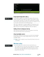
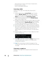
Page 52: ...ge on the unit to confirm which wireless device is connected to the unit 4 Enter the Network Key in the tablet to connect to the network 5 Open the GoFree application the unit should be automatically detected The name displayed will be either the default or that assigned in the Device Name setting If the unit does not appear follow the on screen instructions to manually find the device 6 Select th...

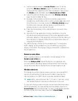
Page 53: ...nually find the device The MFD s display is shown on the smartphone To change the MFD s display on the smartphone use the MFD to change the display on the MFD The display change on the MFD is reflected on the smartphone Remote controllers When a wireless device is connected it should appear in the Remote controllers list Selecting Always allow means the device can automatically connect without nee...

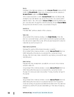
Page 54: ... its network key and connect to it Network Name SSID Displays the name of the internal wireless network Only visible if the internal wireless is set to Access Point Internal Wifi mode when the device is selected You can select it and change the internal wireless network to any name you want for easy identification Network Key Required by the smartphone or tablet to connect to the internal wireless...

Page 55: ... device The Vulcan Series must be running Iperf server before initiating the test from the tablet On exiting the page Iperf automatically stops running DHCP Probe The wireless module contains a DHCP server that allocates IP addresses for all the MFDs and Echosounder in a network If integrating with other devices such as a 3G modem or satellite phone other devices in the network may also be acting ...

Page 56: ...provide support related to their use Internal Wireless Select this option to enable or disable the internal wireless module Disabling wireless when not in use reduces the unit s power consumption NMEA 2000 setup Receive waypoint Select this option to allow another device capable of creating and exporting waypoints via NMEA 2000 to transfer directly to this unit Send waypoint Select this option to ...

Page 57: ...elf and to supported network devices with files read off a memory card inserted in the card reader Before initiating an update to the unit itself be sure to back up any potentially valuable user data Network analyzer and service assistant The system has a built in service assistant that creates a report of the devices installed on the NMEA 2000 network such as the software versions serial numbers ...

Page 58: ...abase backup You can export all Waypoints Routes and Tracks or export only those contained within a specific region If Export Region is selected the chart page will be displayed centered on vessel location Using the touch screen adjust the red boundary box to outline the area to be exported The export option offers different file formats to save as User Data File version 5 This is used to import a...

Page 59: ...ccidentally deleted return to the files page select the backed up file and then Import View file details for creation date Software upgrades The update file must be loaded to the root directory of the memory card The update may be initiated at boot up insert the memory card into the card reader before turning the unit on boot the unit and follow the on screen instructions Alternatively in the File...

Page 60: ...s toolbar option and select the update file under Memory card 2 Select the Upgrade option presented when the file is highlighted A list should appear displaying any compatible devices the update file applies to In most cases this will be a single device Ú Note If no device is shown check that the device to be updated has power and run any outstanding updates for the unit first 3 Select the device ...

Page 61: ...er adapter 7 unit accessories Part number Description 000 14228 001 Sun cover 000 14229 001 Panel mount kit 000 12372 001 U bracket 000 14230 001 Bezel replacement 000 00128 00 Power cable 000 13313 00 7 to 9 pin transducer adapter 9 unit accessories Part number Description 000 13701 001 Sun cover 000 13699 001 Panel mount kit 000 13702 001 U bracket 000 13700 001 Bezel replacement 000 00128 001 P...

Page 62: ...ription 000 14152 001 Sun cover 000 14246 001 Panel mount kit 000 14148 001 U bracket 000 14247 001 Bezel replacement 000 00128 001 Power cable 000 13313 001 7 to 9 pin transducer adapter 62 Accessories Vulcan R Series Installation Manual ...

Page 63: ...7237 Heading Track Control 127245 Rudder 127250 Vessel Heading 127251 Rate of Turn 127257 Attitude 127258 Magnetic Variation 127488 Engine Parameters Rapid Update 127489 Engine Parameters Dynamic 127493 Transmission Parameters Dynamic 127503 AC input status 127504 AC Output Status 127505 Fluid Level 127506 DC Detailed Status 127507 Charger Status 127508 Battery Status 127509 Inverter Status 128259...

Page 64: ...oss Track Error 129283 Cross Track Error 129284 Navigation Data 129539 GNSS DOPs 129540 GNSS Sats in View 129794 AIS Class A Static and Voyage Related Data 129801 AIS Addressed Safety Related Message 129802 AIS Safety Related Broadcast Message 129808 DSC Call Information 129809 AIS Class B CS Static Data Report Part A 129810 AIS Class B CS Static Data Report Part B 130074 Route and WP Service WP L...

Page 65: ...Water Depth 128275 Distance Log 129025 Position Rapid Update 129026 COG SOG Rapid Update 129029 GNSS Position Data 129283 Cross Track Error 129284 Navigation Data 129285 Route Waypoint Data 129539 GNSS DOPs 129540 GNSS Sats in View 130074 Route and WP Service WP List WP Name Position 130306 Wind Data 130310 Environmental Parameters 130311 Environmental Parameters 130312 Temperature 130577 Directio...

Page 66: ... screen multi touch Viewing angles in degrees typicalvalue contrastratio 10 Left right 70 top 50 bottom 60 Electrical Supply voltage 12 V DC 10 17 V DC min max Recommended fuse rating 3 A Protection Protection reverse polarity and temporary over voltage to 18 V Power consumption 5 unit 12 W 900 mA 13 5 V 7 unit 12 W 900 mA 13 5 V 9 unit 12 W 900 mA 13 5 V 12 unit 20 W 1500 mA 13 5 V Environmental ...

Page 67: ...t 5 pin connector 12 unit 1 port 5 pin connector NMEA 2000 1 port Micro C Sonar 1 port 9 pin connector Data card slot 5 unit 1 slot microSD 7 unit 1 slot microSD 9 unit 2 slot microSD 12 unit 2 slot microSD Wireless Internal 802 11b g n Physical Dimensions W x H x D Refer to Dimensionaldrawings on page 68 Weight display only 5 unit 0 53 kg 1 16 lbs 7 unit 0 91 kg 2 lbs 9 unit 1 32 kg 2 9 lbs 12 un...

Page 68: ...120 mm 4 72 94 0 mm 3 70 117 5 mm 4 62 58 0 mm 2 28 136 0 mm 5 35 7 unit dimensional drawings 197 0 mm 7 76 220 0 mm 8 66 126 9 mm 5 00 74 7 mm 2 94 8 0 mm 0 32 141 0 mm 5 56 154 9 mm 6 10 202 2 mm 7 96 61 9 mm 2 44 9 68 Dimensional drawings Vulcan R Series Installation Manual ...

Page 69: ... 94 184 0 mm 7 24 170 0 mm 6 69 8 0 mm 0 31 90 0 mm 3 54 79 0 mm 3 11 12 unit dimensional drawings 310 0 mm 12 20 74 7 mm 2 94 323 5 mm 12 74 219 1 mm 8 63 233 2 mm 9 18 8 0 mm 0 32 95 0 mm 7 74 110 6 mm 4 36 Dimensional drawings Vulcan R Series Installation Manual 69 ...

Page 70: ...70 Dimensional drawings Vulcan R Series Installation Manual ...

Page 71: ......

Page 72: ... 988 11099 003 ...

Reviews: