background image

www.bandg.com

Vulcan

 Series

INSTALLATION  MANUAL

ENGLISH

Summary of Contents for Vulcan Series

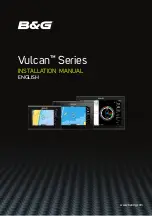
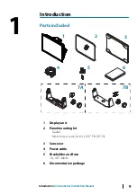
Page 1: ...www bandg com Vulcan Series INSTALLATION MANUAL ENGLISH...

Page 2: ......

Page 3: ...al represents the product as at the time of printing Navico Holding AS and its subsidiaries branches and affiliates reserve the right to make changes to specifications without notice Governing languag...

Page 4: ...radiate radio frequency energy and if not installed and used in accordance with the instructions may cause harmful interference to radio communications However there is no guarantee that the interfer...

Page 5: ...ection or a pay per MB type internet connection may require large data usage Your service provider may charge you based on the amount of data you transfer If you are unsure contact your service provid...

Page 6: ...NMEA and NMEA 2000 are trademarks of the National Marine Electronics Association SD and microSD are trademarks of SD 3C LLC 6 Preface Vulcan Series Installation Manual...

Page 7: ...ons 21 Power control connection 24 External alarm 24 Connecting control devices 24 NMEA 2000 27 Echosounder 28 Radar connector 30 System setup 30 Turning the system on and off 30 First time startup 30...

Page 8: ...52 3rd party support 52 FUSION Link integration 52 CZone 54 Naviop 55 Appendix 55 Technical specifications 57 Dimensional drawings 59 Supported data 8 Contents Vulcan Series Installation Manual...

Page 9: ...LI SH InstallationManual ban dg c om ENGLI SH InstallationManual ban dg c om 1 2 3 4 5 6 7A 7B 1 Display unit 2 Panel mounting kit Gasket Mounting screws 4x 4 x 3 4 PN HD SS 3 Sun cover 4 Power cable...

Page 10: ...9 units U bracket plastic Mounting screws 4x 10 x 3 4 PN HD SS Bracket knobs 2x B Bracket mounting kit 12 unit U bracket metal Mounting screws 4x 10 x 3 4 PN HD SS Bracket knobs 2x 10 Introduction Vul...

Page 11: ...Front controls 2 1 1 Touch screen 2 Power key Press and hold to turn the unit ON OFF Press once to display the System Controls dialog Introduction Vulcan Series Installation Manual 11...

Page 12: ...or copy files to a chart card Doing so can damage chart information on the chart card The card reader door is opened by pulling the rubber cover open The card reader door should always be securely shu...

Page 13: ...ar connections 1 2 3 4 RADAR NMEA2000 POWER SONAR 1 Radar radar Ethernet connection 2 NMEA 2000 data input output 3 Power 12 V DC supply input 4 Sonar Sonar CHIRP Sonar ForwardScan Introduction Vulcan...

Page 14: ...e parts Do also consider The free space around the unit to avoid overheating The mounting surface s structure and strength with regard to the weight of the equipment Any mounting surface vibration tha...

Page 15: ...is important to test the WiFi performance before the location of the unit is decided Construction material steel aluminum or carbon and heavy structure might affect WiFi performance The following guid...

Page 16: ...ded to overcome poor performance A B C A Optimal location above deck B Less effective location C Not recommended location Note Consider the lateral swinging if mounting the GPS sensor high above the s...

Page 17: ...2 Mark the screw locations using the bracket as a template and drill pilot holes Use fasteners suited to the mounting surface material If the material is too thin for self tappers reinforce it or mou...

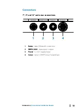
Page 18: ...18 Installation Vulcan Series Installation Manual...

Page 19: ...To release the locking tabs gently insert a thin object between the bezel and the screen frame When the first locking tab is released and an opening is visible carefully release the remaining locking...

Page 20: ...imp and insulate all wiring connections if extending or shortening the cables Extending cables should be done with suitable crimp connectors or solder and heat shrink Keep joins as high as possible to...

Page 21: ...Connecting to an external alarm Blue wire _ 1 2 3 5 6 4 1 Power cable 2 12 V positive wire red shown with fuse holder fitted 3 12 V negative wire black 4 Power control wire yellow 5 Alarm wire blue 6...

Page 22: ...o unit 2 Positive wire red 3 Ground wire black 4 Power control wire yellow 5 Alarm wire blue Power Control to supply positive auto on Device will turn on immediately when power is applied Common the y...

Page 23: ...t engines Connect the yellow wire to the accessories output of the engine key switch Note Engine start batteries and house batteries should have a common ground connection _ 5 1 2 3 4 6 1 Power cable...

Page 24: ...still display the alarm information For information about configuring alarms refer to the Alarms section in the Operator Manual For sirens that draw more than 1 Amp use a relay _ A B D C Buzzer _ A B...

Page 25: ...of the locations of all products to be connected typically in a bow to stern layout The following guidelines apply The total length of the backbone should not exceed 100 meters 328 ft A single drop ca...

Page 26: ...a 3 A fuse For smaller systems connect power at any location in the backbone For larger systems connect power at a central point in the backbone to balance the voltage drop of the network Make the in...

Page 27: ...te A 7 pin transducer cable can be connected to a 9 pin port using a 7 pin to 9 pin adaptor cable However if the transducer has a paddle wheel speed sensor the water speed data will not be displayed o...

Page 28: ...ta and synchronization of user created data It is recommended that each device in the system is connected to the Ethernet network No special setup is required for establishing an Ethernet network Note...

Page 29: ...Key Purpose Color 4 Receive negative RX Orange 5 Shield Bare Wiring Vulcan Series Installation Manual 29...

Page 30: ...ttings You can perform further setup and later change settings using the system settings dialogs System setup sequence 1 General settings refer to Systemsettings on page 31 Make general settings as de...

Page 31: ...he PIN code and store it in a safe place When you establish password protection the PIN code must be entered when any of the following are selected After the correct PIN code is entered all of them ca...

Page 32: ...ystem Rotating mast compensation If the vessel is fitted with a rotating mast it will impact any sensors or radar mounted to it Provided the mast is also fitted with a sensor to measure rotation the e...

Page 33: ...true wind calculations Note The autopilot cannot be operated using COG as the heading source COG cannot be calculated when stationary GPS offset start line configuration In order for the start line fe...

Page 34: ...f all available alarm options in the system with current settings From this list you can activate deactivate and change alarm limits Siren enable Enables or disables the internal and external audio al...

Page 35: ...dual radar mode are represented twice in the source list with an A and B suffix Radar status Displays scanner information and scanner features primarily used for information and to assist with fault...

Page 36: ...he screen with the center line of the vessel This will compensate for any slight misalignment of the scanner during installation Misalignment that is not corrected for will compromise target tracking...

Page 37: ...lly should not need to be adjusted However if there is significant metallic clutter around the radar sidelobe suppression may need to be increased To adjust the sidelobe suppression value 1 Set radar...

Page 38: ...o standby The antenna will stop rotating at the desired offset Adjust local interference reject Interference from some onboard sources can interfere with the Broadband radar One symptom of this could...

Page 39: ...tings View sonar log Used to view recordings The log file is displayed as a paused image and you control the scrolling and display from the menu You can use the cursor on the image measure distance an...

Page 40: ...the bottom set the offset equal to the vertical distance between the transducer and the water surface B positive value For depth below transducer set the offset to 0 Installation Use this dialog to se...

Page 41: ...boat in the water or from the transducer to the water surface B A B A To show the depth from the lowest point of the vessel to the bottom set the offset equal to the vertical distance between the tran...

Page 42: ...range 1 30 seconds Default is 1 second Water temperature calibration Temperature calibration is used to adjust the water temperature value from the transducer It may be required to correct for locali...

Page 43: ...hosounder source for any unit on the network Unselect this option on units which do not have a transducer connected Network Echosounder Select to share transducers from this unit with other units conn...

Page 44: ...areful of changing settings after commissioning is completed H5000 specific installation settings For setup and commissioning of the H5000 refer to the documentation included with the H5000 system NAC...

Page 45: ...ross all tanks Fuel remaining measurement The Fuel remaining measurement can be determined from fuel used by engine s or fuel level from tank sensors Nominal fuel consumption is required to set the sc...

Page 46: ...g if set in Calibrate Only Navico devices can be reset Calibrate Calibration may be required to accurately match measured flow with actual fuel flow Access calibration from the Refuel dialog Calibrati...

Page 47: ...number of tanks must be set in Vessel Setup dialog initiated from the Fuel setting options page to allow discrete tank assignment of the Fluid Level devices Select Device list on the Network page and...

Page 48: ...es Data sources provide live data to the system When a device is connected to more than one source providing the same data the user can choose the preferred source Before commencing with source select...

Page 49: ...natively use a data source independently from other units If the unit is part of a source group all source selection changes will affect all units belonging to the same group Note In order to enable g...

Page 50: ...rs are most likely indicating issues with the physical network which can be resolved by correcting termination reducing backbone or drop lengths or reducing the number of network nodes devices UDB Pro...

Page 51: ...eive waypoint option must be set to ON before the waypoint is created in the sending device The sending device the send waypoint option must be set to ON before the waypoint is created Send waypoint A...

Page 52: ...he two networks but allows data to be freely shared between both sides The Interface Bridge can also be used for expansion of the NMEA 2000 network when the maximum node limit node any device connecte...

Page 53: ...ch setting This setting is unique for each device Typically it is set after the configuration file already exists on the CZone system but it may also be set in advance To do so access the CZone menu o...

Page 54: ...he same NMEA 2000 network as a Naviop Loop system this device can be used to operate the Naviop Loop system For details refer to the documentation following the Naviop system 54 3rd party support Vulc...

Page 55: ...17 V DC min max Recommended fuse rating 3 A Protection Protection reverse polarity and temporary over voltage to 18 V Power consumption 7 unit 12 W 900 mA at 13 5 V 9 unit 12 W 900 mA at 13 5 V 12 un...

Page 56: ...C Sonar 1 port 9 pin connector Data card slot 7 unit 1 slot microSD 9 unit 2 slot microSD 12 unit 2 slot microSD Wireless Internal 802 11b g n Physical Weight display only 7 unit 0 91 kg 2 lbs 9 unit...

Page 57: ...9 mm 5 00 74 7 mm 2 94 8 0 mm 0 32 141 0 mm 5 56 154 9 mm 6 10 202 2 mm 7 96 61 9 mm 2 44 9 unit 242 0 mm 9 52 263 0 mm 10 35 24 0 mm 0 94 184 0 mm 7 24 170 0 mm 6 69 8 0 mm 0 31 90 0 mm 3 54 79 0 mm...

Page 58: ...310 0 mm 12 20 74 7 mm 2 94 323 5 mm 12 74 219 1 mm 8 63 233 2 mm 9 18 8 0 mm 0 32 95 0 mm 7 74 110 6 mm 4 36 58 Appendix Vulcan Series Installation Manual...

Page 59: ...Info 126998 Configuration Information 127233 Man Overboard Notification MOB 127237 Heading Track Control 127245 Rudder 127250 Vessel Heading 127251 Rate of Turn 127252 Heave 127257 Attitude 127258 Ma...

Page 60: ...aids to Navigation 129283 Cross Track Error 129284 Navigation Data 129539 GNSS DOPs 129540 AIS Class B Extended Position Report 129545 GNSS RAIM Output 129549 DGNSS Corrections 129551 GNSS Differenti...

Page 61: ...Current File and Status 130570 Entertainment Library Data File 130571 Entertainment Library Data Group 130572 Entertainment Library Data Search 130573 Entertainment Supported Source Data 130574 Enter...

Page 62: ...128267 Water Depth 128275 Distance Log 129025 Position Rapid Update 129026 COG SOG Rapid Update 129029 GNSS Position Data 129283 Cross Track Error 129285 Navigation Route WP Information 129284 Naviga...

Page 63: ...w x x VTG Course over ground and ground speed x x ZDA Time and date x x TX RX Navigation Na me Description RX TX AAM Waypoint arrival alarm x APB Heading track controller autopilot sentence B x BOD Be...

Page 64: ...ance x x VHW Water speed and heading x x TX RX Compass Na me Description RX TX HDG Heading deviation and variation x x HDT Heading true x THS True heading and status x x ROT Rate of turn x TX RX Wind...

Page 65: ...t bridged to or from NMEA 2000 TX RX MARPA Na me Description RX TX TLL Target latitude and longitude x TTM Tracked target message x Note These are only output sentences TX RX Radar Na me Description R...

Page 66: ...Na me Description RX TX VBW Dual ground water speed x XDR Transducer measurement x x 66 Appendix Vulcan Series Installation Manual...

Page 67: ......

Page 68: ...11099 004 www bandg com Reg U S Pat Tm Off and common law marks Visit www navico com intellectual property to review the global trade mark rights and accreditations for Navico Holding AS and other ent...

Reviews: