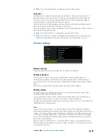
Fuel remaining measurement
The Fuel remaining measurement can be determined from fuel used by engine(s), or fuel
level from tank sensors. Nominal fuel consumption is required to set the scale on the fuel
economy gauge. This value should be determined from experience, over time. Alternatively
the boat builder or designer may be able to give an approximate value to use.
Ú
Note:
Fuel remaining measurement taken from level sensors while underway can get
inaccurate readings due to vessel movement.
Ú
Note:
Nominal fuel consumption setting should be determined taking into account
typical vessel loads. That is, filled fuel and water tanks, stowed tender, supplies, etc.
Fuel flow configuration
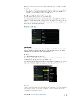
After the number of engines is set, it is required to set which fuel flow sensor is connected to
which engine. Under Device list on the Network page, view the Device Configuration dialog
for each sensor, and set the Location to match the engine the device is connected to.
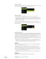
Unconfigure
- defaults the device which clears all user settings.
Reset Fuel Flow
- restores only the Fuel K-Value setting, if set in Calibrate. Only Navico
devices can be reset.
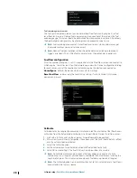
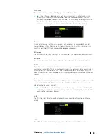
Calibrate
Calibration may be required to accurately match measured flow with actual fuel flow. Access
calibration from the Refuel dialog. Calibration is only possible on Navico’s Fuel Flow sensor.
1.
Start with a full tank and run the engine as it would normally be operated.
2.
After at least several liters (a few gallons) have been used, the tank should be fully refilled,
and the Set to full option selected.
3.
Select the Calibrate option.
4.
Set the actual amount used based on amount of fuel added to the tank.
5.
Select OK to save settings. The Fuel K-Value should now show a new value.
Ú
Note:
To calibrate multiple engines repeat the steps above, one engine at a time.
Alternatively, run all engines simultaneously, and divide the Actual amount used by the
number of engines. This assumes reasonably even fuel consumption on all engines.
Ú
Note:
The Calibrate option is only available when Set to full is selected, and a Fuel Flow is
connected and set up as a source.
28
Software setup
| Zeus3 Glass Helm Installation Manual
Summary of Contents for Zeus3 Glass Helm
Page 1: ...ENGLISH Zeus3 GlassHelm Installation Manual www bandg com ...
Page 2: ......
Page 45: ......
Page 46: ... 988 11997 001 ...

