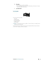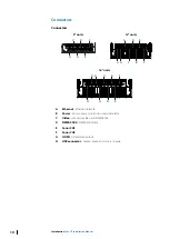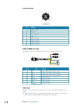
Connector details
7
6
2
4
8
3
5
1
Unit socket (male)
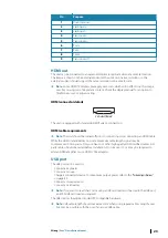
Pin
Purpose
1
Video 1 Ground
2
Video 1 (+)
3
Video 2 Ground
4
Video 2 (+)
5
NMEA 0183 TX_B
6
NMEA 0183 TX_A
7
NMEA 0183 RX_A
8
NMEA 0183 RX_B
VIDEO IN/NMEA 0183 cable
Ú
Note:
This cable (part number 000-00129-001) is not included with the unit.
D
E
F
G
A
B
C
Key
Color
Purpose
A
Video in/data cable connector to unit
B
Red
Camera input 1 (RCA coaxial connector)
C
Green
Camera input 2 (RCA coaxial connector)
D
Blue
NMEA 0183 TX_B
E
Yellow
NMEA 0183 TX_A
F
Green
NMEA 0183 RX_A
G
Orange
NMEA 0183 RX_B
Video input
The unit can be connected to a composite video source, and display video images on its
display.
Ú
Note:
Camera cables are not supplied, and will need to be selected to suit termination -
RCA at the unit, and typically BNC or RCA plug at the camera end.
20
Wiring
| Zeus³S Installation Manual
Summary of Contents for Zeus3S
Page 1: ...ENGLISH Zeus3 S Installation Manual www bandg com...
Page 2: ......
Page 50: ......
Page 51: ...988 12599 001...

