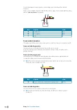

1
Point the vessel towards a stationary isolated object, or towards a far range AIS
target where the AIS icon matches the radar echo.
2
Adjust the coarse and fine bearing alignment so that the heading line touches the
end of the selected object, or the radar target matches the AIS target.
Ú
Note:
Adjustments to bearing alignment has to be done before Use mast rotation is
enabled.
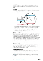
Sidelobe suppression
Occasionally false target returns can occur adjacent to strong target returns such as large
ships or container ports. This occurs because not all of the transmitted radar energy can be
focused into a single beam by the radar antenna, a small amount of energy is transmitted in
other directions. This energy is referred to as sidelobe energy and occurs in all radar systems.
The returns caused by sidelobes tend to appear as arcs.
Ú
Note:
This control should only be adjusted by experienced radar users. Target loss in
harbor environments may occur if this control is not adjusted correctly.
When the radar is mounted where there are metallic objects near the radar, sidelobe energy
increases because the beam focus is degraded. The increased sidelobe returns can be
eliminated using the sidelobe suppression control.
By default, this control is set to auto and normally should not need to be adjusted. However,
if there is significant metallic clutter around the radar, sidelobe suppression may need to be
increased.
To adjust the sidelobe suppression value:
1.
Set radar range to between 1/2 nm to 1 nm and the sidelobe suppression to auto
2.
Take the vessel to a location where sidelobe returns are likely to be seen. Typically, this
would be near a large ship, container port, or metal bridge.
3.
Traverse the area until the strongest sidelobe returns are seen.
4.
Change auto sidelobe suppression to OFF, then adjust the sidelobe suppression control
just enough to eliminate the sidelobe returns. You may need to monitor 5-10 radar
sweeps to be sure they have been eliminated.
5.
Traverse the area again and readjust if sidelobes returns still occur.
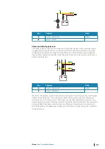
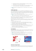
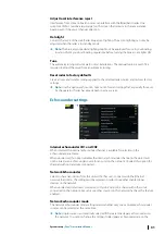
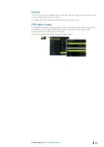
Sector blanking
Radar installed in close proximity to a mast or structure could cause unwanted reflections or
interference to appear on the radar image. Use the sector blanking feature to stop the radar
from transmitting on up to four sectors in the image.
Ú
Note:
Sectors are setup relative to the heading line of the radar. The bearing of the
sector is measured from the center line of the sector.
Ú
Note:
Sector blanking should be applied very carefully to avoid reducing the radar’s
usefulness in identifying valid and potentially dangerous targets.
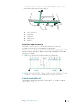
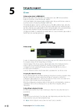
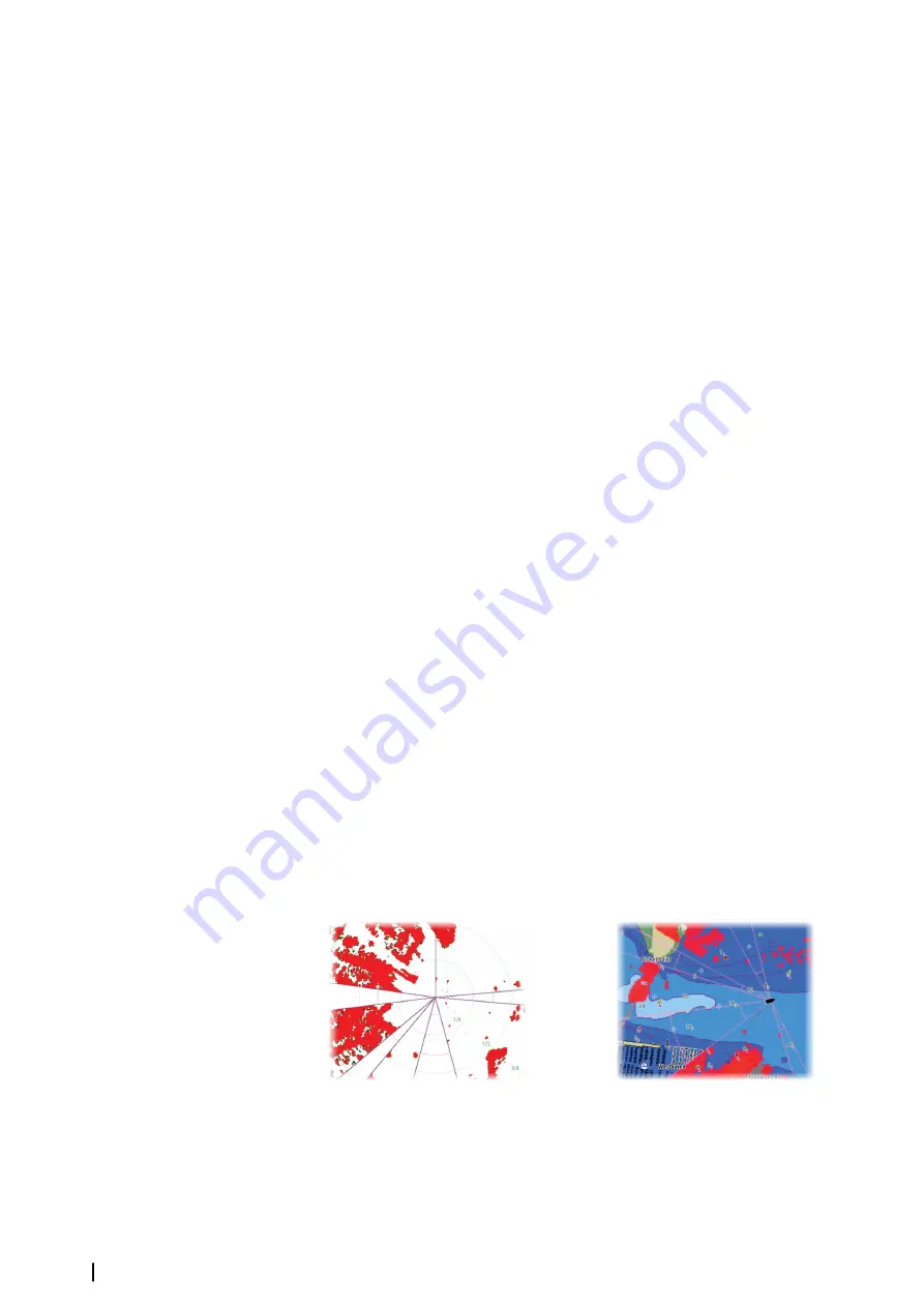
Main radar PPI
Radar overlay on a chart
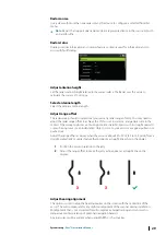
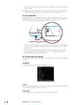
Adjust open array park angle
The park angle is the final resting position of the antenna relative to the heading line of the
radar when the radar is set to standby. The antenna will stop rotating at the desired offset.
30
System setup
| Zeus³S Installation Manual
Summary of Contents for Zeus3S
Page 1: ...ENGLISH Zeus3 S Installation Manual www bandg com...
Page 2: ......
Page 50: ......
Page 51: ...988 12599 001...