A
B
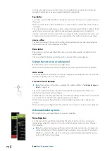
When true motion is selected, the true motion reset option is available from the menu. This
allows for manually resetting the radar image and vessel symbol to its starting position.
Ú
Note:
True motion is only available when the PPI is in either north up or course up
orientation mode.
Offsetting the PPI center
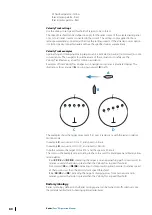
You can set the antenna position origin to a different location on the radar PPI. The options
described in the next sections are available.
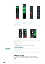
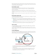
PPI center: Center
PPI center: Look Ahead
PPI Center: Offset
Ú
Note:
The bearing scale is according to the Consistent Common Reference Point (CCRP),
while the offset sets the radar antenna position on the PPI. The maximum off-centering
allowed is 75% of the radius at the current range. This may result in the CCRP being
outside of the bearing scale. In such cases the measurements are still taken by the CCRP
and the bearing scale is compressed accordingly.
Center
The Center option resets the antenna position to the center of the PPI.
Look ahead
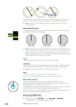
The Look ahead option is used to maximize the view ahead of the vessel. When selected the
PPI center is placed at 70% of the radius of the PPI, 180° opposite the top of the display.
Ú
Note:
Look ahead is only available for Heading Up radar orientation.
Offset
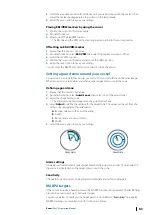
This option allows you to use the cursor for selecting the PPI center.
Move the cursor to the preferred offset position, and confirm your selection.
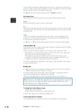
EBL/VRM markers
The electronic bearing line (EBL) and variable range marker (VRM) allows quick
measurements of range and bearing to vessels and landmasses within radar range. Two
different EBL/VRMs can be placed on the radar image.
The EBL/VRMs are by default positioned from the center of the vessel. It is, however, possible
to offset the reference point to any selected position on the radar image.
When positioned, you can turn the EBL/VRM on/off by selecting the relevant markers on the
data bar, or by deselecting the marker from the menu.
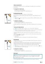
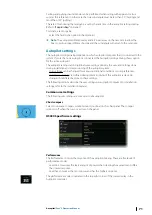
Defining an EBL/VRM marker
1.
Ensure that the cursor is not active
2.
Activate the menu, select
EBL/VRM
, then select
EBL/VRM 1
or
EBL/VRM 2
- The EBL/VRM is now positioned on the radar image
82
Radar
| Zeus³S Operation Manual
Summary of Contents for Zeus3S
Page 1: ...ENGLISH Zeus3 S Operator Manual www bandg com...
Page 2: ......
Page 139: ......
Page 140: ...988 12586 001...

