background image

Bandit 240 PB Installation and User Guide

5

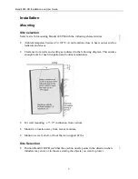
Mounting procedure—wall

1.


Select a mounting location. Be sure the location you select complies with the
requirements listed in the section “Site selection” on page 3.

2.


If you ordered the optional Handy-Boy jig, place Bandit 240 PB on the jig.

3.


Connect power wires to Bandit.

4.


Mark and drill holes to ½" depth.

5.


Attach the mounting plate using screws.

6.


Position and secure Bandit on the mounting plate.

Proceed to “Electrical Connection” on page 6.

Mounting procedure—floor

1.


Select a mounting location. Be sure the location you select complies with the
requirements listed in the section “Site selection” on page 3.

2.


If you ordered the optional Handy-Boy jig, place Bandit 240 PB on the jig.

3.


Connect power wires to Bandit.

4.


On the floor, mark and drill holes to ½" depth.

5.


Attach the mounting plate using screws.

6.


Position and secure Bandit on the mounting plate.

Proceed to “Electrical Connection” on page 6.

Mounting procedure—concealed location

1.


Select a mounting location. Be sure the location you select complies with the
requirements listed in the section “Site selection” on page 3. In particular, ensure you
have enough ventilation to allow heat dissipation.

2.


If you ordered the optional Handy-Boy jig, place Bandit 240 PB on the jig.

3.


Connect power wires to Bandit.

4.


On the floor or wall, mark the location of Bandit.

5.


On the door concealing Bandit, mark and drill a hole with 2" diameter.

6.


On the mounting surface, mark and drill holes to ½" depth.

Summary of Contents for 240 PB

Page 1: ...andit 240 PB Installation and User Guide 2006 All rights reserved Bandit Solutions Inc Distributed by Detection Dynamics Inc 6606 N Lamar Blvd Suite 300 Austin Texas 78752 512 453 1133 www cctvpros co...

Page 2: ...PB open the shipping box and verify you have received the following items Bandit 240 PB Hypak 3 Allen wrench Bandit software disk Optional hardware you may have ordered such as mounting kits Complianc...

Page 3: ...rance from walls and ceiling as indicated in the following diagram This ensures enough room for heat dissipation and routine maintenance For wall mounting a 5 15 inclination from vertical Mount in a l...

Page 4: ...t surface to block the ejection is 20 feet 6 meters away When installing multiple nozzles position the nozzles so they expel fog in a manner that avoids double clouding of the same area Suggested poin...

Page 5: ...on page 3 2 If you ordered the optional Handy Boy jig place Bandit 240 PB on the jig 3 Connect power wires to Bandit 4 On the floor mark and drill holes to depth 5 Attach the mounting plate using scr...

Page 6: ...oceed to Electrical Connection Electrical Connection Caution Installation of Bandit 240 PBrequires a 110 VAC power source and a dedicated ground Be sure you follow all local safety requirements and bu...

Page 7: ...and the white wire to Grdout See Figure 1 3 If required connect the blue and black wires to the Ta and Tb sabotage loop LEDs The following table lists the LEDs on Bandit s front cover and their corre...

Page 8: ...r or contact Technical Support Maintenance Testing fog ejection Perform a fog ejection test once a year To perform the test push the test button on the Control Box see figure to right Caution Notify a...

Page 9: ...ons Characteristic Value Dimensions 10 6 wide 14 4 high 10 deep Weight 62 pounds Max mains supply failure 2 hours Maximum reaction time 1 second between alarm signal and fog ejection Fog ejection imag...

Page 10: ...oubleshooting and Technical Support Leave all repairs to authorized persons and or the manufacturer For technical support contact your distributor Detection Dynamics Inc 6606 N Lamar Blvd Suite 300 Au...

Reviews: