
Bandit 240 PB Installation and User Guide
7
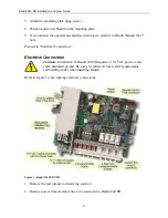
3.
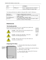
Open the rear cover on Bandit.
4.
Locate the 3-way terminal block for 110 VAC power.
5.
Connect power leads as follows: Red to N, black to L, and ground to ground.
6.
Route power cable through strain relief.
7.
Reapply power to electrical line.
8.
With a volt meter, test power at N and L terminals. Verify power is 110 VAC.
9.
Replace the real jumper.
Connecting Accessories
You can install accessories to Bandit 240 PB that require 12 VDC power. Examples of
accessories include the Jumbo LED or an external siren.
1.
Mount the accessory.
2.
Connect the red wire to the +12V power supply, and the white wire to Grdout (See
Figure 1).
3.
If required, connect the blue and black wires to the Ta and Tb sabotage loop.
LEDs
The following table lists the LEDs on Bandit’s front cover and their corresponding
indications.
LED
Indication
Solid green
Bandit is operational.
OK
Blinking green
Bandit is warming up; up to 50 minutes are
required for warm up after cold start.
Guard
Solid red
Bandit in guard mode.
Solid red
Bandit in alarm mode.
Alarm
Blinking red
Bandit in panic mode.
Slow blinking red
Internal failure detected.
Failure
Fast blinking red
Technical adjustment required. Possible
causes include control box is switched on,
wrong type of HY-3 pack installed, real
jumper not plugged in (see Figure 1).
HY-3
Blinking red
Less than 15 seconds of fog ejection time
remaining in canister. Replace or refill
canister.