Bandit 240 PB Installation and User Guide
8
LED
Indication
Power
Blinking red
Power supply disconnected or main fuse
blown
and
Bandit not in guard mode.
The following table lists the conditions of the green LED on the HY-3 Pak sleeve.
Solid green
Canister installed properly and armed.
Blinking green
Canister not installed correctly or wrong canister installed.
Replace canister.
Fast blinking green
Low fluid in canister. Replace canister.
Green off
Communication failure. Clean electrical contacts, replace
canister, or contact Technical Support.
Maintenance
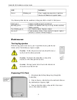
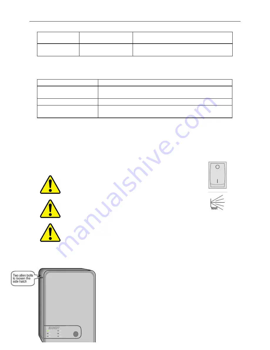
Testing fog ejection
Perform a fog ejection test once a year. To perform the test, push the test
button on the Control Box (see figure to right).
Caution
— Notify all persons in test area about the test, as
well as local fire safety personnel.
Caution
— Nobody in the immediate vicinity of the
nozzles or in the direct path of ejection.
Caution
— During ejection do not look in the direction of
the nozzle closer than 26 feet.
Replacing HY-3 Pack
1.
If installed, disarm the sabotage loop through the
Control Box.
2.
Unscrew the two Allen bolts on the side hatch. Remove
the side hatch (see figure to right).
3.
Unscrew the Allen bolts on the old HY-3 Pack and
remove the canister assembly.