background image

10 


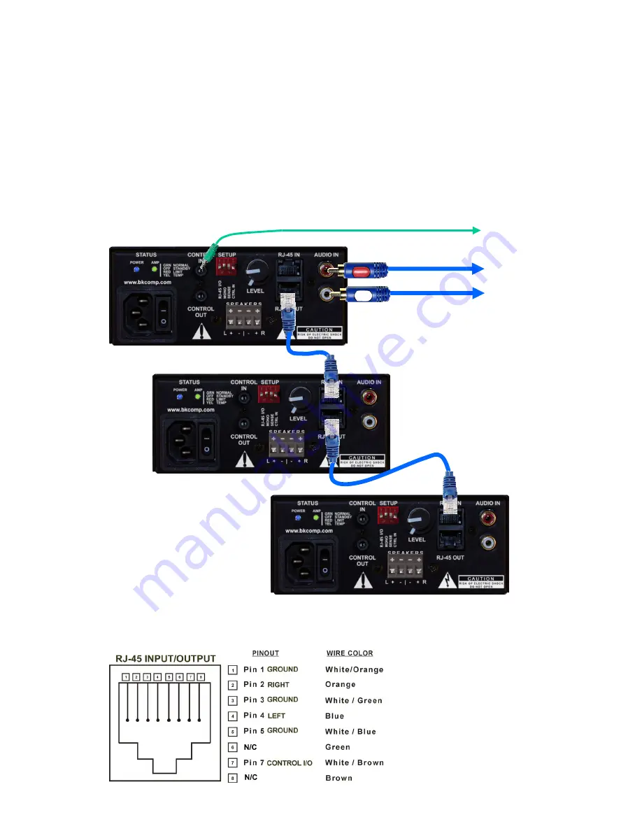
Input and Output Connections through RJ-45 

The AV Brick Amplifiers have RJ-45 inputs that are designed to connect mul-
tiple AV amplifiers. A straight through CAT-5 cable is needed to send signal 
and a optional control output from one AV amplifier to another. When using 
the RJ-45 input from one to another, signal is always sent. If a trigger is to be 
sent from one brick amplifier to another when using the RJ-45 connection, set 
the RJ-45 I/O switch AND the CTRL IN to the ON position on BOTH amplifi-
ers as shown. Shown below is a total of three Brick Amplifiers connected with 
the RJ-45 connection. The source comes into the first amplifier and the same 
signal is sent to the other amplifiers from the output of the first amplifier to the 
input of the second and so forth.  

From Preamplifier 

AV Amplifier 

AV Amplifier 

AV  Amplifier 

Note: 

Up to 

eight separate

 AV Brick Amplifiers can be connected by the RJ-45 Input and Output 

connections. The max length of total CAT-5 cable can be up to 

300

 feet from the RJ-45 output of 

the first AV amplifier to the RJ-45 input on the last AV amplifier. 

RJ-45 Input/Output Drive Pinout 
 

It is suggested to ONLY use the RJ-
45 Inputs and Outputs to connect 
multiple AV Brick Amplifiers.  
 
CAT-5 RJ-45 pinouts use the 

T568B


standard. 

Summary of Contents for AV100.2

Page 1: ...B K Components Ltd AV 30 2 60 2 100 2 Two Channel Digital Amplifier User Manual 14224 101607...

Page 2: ...er insures that you have a FACTORY WARRANTY on your B K Components Ltd product If you have any questions concerning your Factory Warranty call B K Components Ltd At 716 656 0026 Upgradability B K is o...

Page 3: ...ess noise with no input signal since the internal circuitry is off when the unit has no signal Gold Plated Connectors Improved sound with minimal signal loss and degradation Control Input One 3 5mm 1...

Page 4: ...4 AV 30 2 60 2 100 2 Front and Back Panel 4 3 2 5 6 7 8 9 10 1...

Page 5: ...s standby on off feature Explained further under Control Trig gers 7 Dip Switch Setup The amplifier uses DIP switches to configure the RJ 45 Input Output mono and muting control Further explained unde...

Page 6: ...nel level controls Two volume controls are provided on the back of the AV amplifiers allowing for separate control of the left and right signals The outer level control adjusts the vol ume of the righ...

Page 7: ...he audio cables from the preamplifier s audio outputs to the ampli fier input channels using RCA interconnects Connect all common controls if using a trigger from the preamplifier to the amplifier Con...

Page 8: ...amplifier is in standby state All B K A V receivers and preamplifiers utilize control output triggers to easily integrate an amplifier into an audio system Shown below is an AV amplifier receiving sig...

Page 9: ...he blue Power LED would still be on Limit When the unit is under conditions of having too much of a signal the Amp Status LED will turn red The audio from the amplifier may also clip distort etc Temp...

Page 10: ...a total of three Brick Amplifiers connected with the RJ 45 connection The source comes into the first amplifier and the same signal is sent to the other amplifiers from the output of the first amplif...

Page 11: ...and turn green when detecting an audio signal from either input CTRL IN When a trigger is needed to take the amplifier in and out of standby state the CTRL IN DIP switch would be enabled This applies...

Page 12: ...ensitivity 1 V 1 W 1 V 1 W 1 V 1 W Gain 28AV or 28 dB 28AV or 28 dB 28AV or 28 dB AC Line Voltage 120 220 240 120 220 240 120 220 240 Level Controls Dual Back Dual Back Dual Back Maximum Output Wire G...

Reviews: