background image

CONTROL INPUT AND OUTPUT 

 
A control (trigger) system is provided on both the AV125.7 and AV125.5 amplifiers to allow remote switching of 
the amplifier’s standby on/off feature. The control input is designed to operate with a source (trigger) of 5-24 volts 
AC or DC. All B&K A/V processors and preamplifiers may easily be utilized to control this standby on/off feature. 
 
In addition your amplifier has a control output circuit to allow control of an external device such as another power 
amplifier, projection screen, power strip, etc. The control output has the capability to source 12VDC @ 125 mA 
(on) or 0 VDC (off). 
 
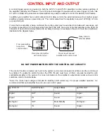
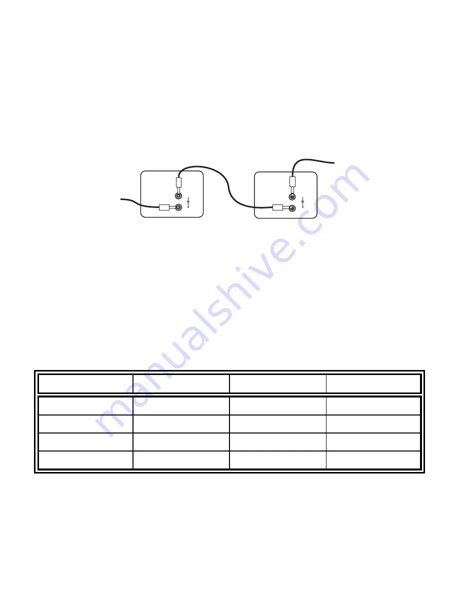
If more that one amplifier is being controlled, the control output may be extended to include each successive unit 
by simply connecting a 1/8” mini-jack cable from the CTRL OUT connector of the first amplifier to the CTRL IN 
connector of next unit (commonly referred to as ‘daisy chaining’). An example of how to connect two amplifiers is 
illustrated in the diagram below. 


Rear view of second

amplifier with control input

Rear view of amplifier

with control input

Daisy chain to
other amplifiers

From preamplifier
rear panel
control output

C O N T R O L I / O

C T R L

I N

C T R L

O U T

1 2 V D C
1 2 5 m A

+

CONTROL IN ALLOWS AMPLIFIER

OPERATION WHEN A 5-24V SIGNAL

IS APPLIED WITH A 3.5mm MINI JACK

C O N T R O L I / O

C T R L

I N

C T R L

O U T

1 2 V D C
1 2 5 m A

+

CONTROL IN ALLOWS AMPLIFIER

OPERATION WHEN A 5-24V SIGNAL

IS APPLIED WITH A 3.5mm MINI JACK


DO NOT POWER MOTORS WITH THE CONTROL OUT CIRCUIT!!! 


If the control function is desired, each unit in the system must remain connected at all times and the control must 
be enabled. To enable the control function, the CTRL IN jack must have a 3.5mm mini-jack inserted for each 
controllable amplifier in the system. For more information on the amplifier’s output status under various control 
conditions, refer to the table below. 
 
*

Note: The control input voltage is intended for 

standby on/off

 control only. For proper amplifier operation, it is 

recommended that each amplifier have its own source of AC power. 


@ CTRL IN 
 

Button Position 

Output Status 

@CTRL OUT 

Signal OUT  Sound Signal 


Signal IN 

Sound Signal 


No Signal 

OUT 

Mute/Standby 

No Signal 
 

No Signal 

IN 

Sound  

Signal 


8

Summary of Contents for AV125.5

Page 1: ...B K S B IMPLY ETTER B K Components Ltd AV125 7 AV125 5 Owner s Manual P N13440 1102...

Page 2: ...B K Components Ltd 2100 Old Union Road Buffalo New York 14227 2725 Phone 1 800 543 5252 or 716 656 0026 Fax 716 656 1291 E mail info bkcomp com Web www bkcomp com ii...

Page 3: ...3 Level Adjustment 4 Inputs 4 XLR Balanced 4 RCA Unbalanced 4 Balanced or Unbalanced Connections 5 Outputs 6 System Installation 7 Making the Connection 7 Control Input and Output 8 Troubleshooting 9...

Page 4: ...the unit is resting on We advise against removing or altering feet Do not stack anything on top of the amplifier processor source etc Leave a minimum of 2 clearance from the top of the amplifier to t...

Page 5: ...y on off with a 5 24 VDC control signal Gold Plated Connectors better sound with minimum signal loss and degradation Toroidal Transformer Efficient shielded transformer that supplies the amplifier wit...

Page 6: ...use is a 12 Amp 250 Volt Slow Bow fuse Replace only with the same type and value fuse 2 AC Input Receptacle for attaching the supplied AC power cord to the amplifier 3 Speaker Outputs for connecting t...

Page 7: ...AMPLIFIER CHANNELS for use with either balanced XLR or RCA unbalanced preamplifier processor line outputs INPUT 4 INPUT 5 XLR BALANCED RCA UNBALANCED INPUT 4 INPUT 5 XLR BALANCED There are seven balan...

Page 8: ...T 4 INPUT 5 INPUT 6 INPUT 7 CTRL IN CTRL OUT 12VDC 125mA XLR BALANCED RCA UNBALANCED CONTROL IN ALLOWS AMPLIFIER OPERATION WHEN A 5 24V SIGNAL IS APPLIED WITH A 3 5mm MINI JACK XLR BALANCED RCA UNBALA...

Page 9: ...H O C K D O N O T O P E N R I S K O F E L E C T R I C S H O C K D O N O T O P E N CHANNEL 6 OUTPUT CHANNEL 7 OUTPUT CHANNEL 5 OUTPUT CHANNEL 4 OUTPUT CHANNEL 3 OUTPUT CHANNEL 2 OUTPUT CHANNEL 1 OUTPUT...

Page 10: ...is recommended that you locate a separate AC power outlet for the amplifier one that is not shared by any other audio component in the system or any other household component This will eliminate the p...

Page 11: ...of second amplifier with control input Rear view of amplifier with control input Daisy chain to other amplifiers From preamplifier rear panel control output CONTROL I O CTRL IN CTRL OUT 12VDC 125mA CO...

Page 12: ...eakers connected out of phase 1 Check all connections making sure that cables are connected to and to Loud hum or buzz on one or more channels 1 Poor ground connection in inter connect cables 1 Check...

Page 13: ...80 Current peak to peak 16 Amps Slew rate 14 V sec Dynamic headroom 1 0 dB S N A weighted 95 dB Voltage gain 28 Line voltage 120 220 240 VAC switchable Dimensions O A 17 w X 16 d X 5 75 h Weight 43 lb...

Page 14: ...B K delivers exceptional value to its customers But what is Upgradability Upgradability is not a guarantee we define it as a philosophy of designing and manufacturing products so that as audio techno...

Page 15: ...I N P U T 1 I N P U T 2 I N P U T 3 I N P U T 4 I N P U T 5 I N P U T 6 I N P U T 7 X L R B A L A N C E D R C A U N B A L A N C E D B K Components Ltd Made in the U S A B K Components Ltd Made in the...

Page 16: ...WWW BKCOMP COM B K Components Ltd 2100 Old Union Road Buffalo New York 14227 Phone 716 656 0026...

Reviews: