background image

Page 4

Features

Overview

Your new AVP series preamplifier from B & K Components, Ltd., is a versatile
audio/video control center.  The AVP preamplifiers are designed to not only sound
sensational, but also to be an attractive, easy-to-use addition to your audio/video
system.  Although you already have a good idea of your preamplifier’s features, we’d
like to take a moment to point out certain highlights.  Following that, the rest of this
section describes the front panels display and controls, remote control and rear panel
features.  The AVP2030 is a two zone preamplifier.

Latest technology audio design - With B & K, you’re assured that the basic
design foundation of your preamplifier provides excellent quality, fidelity, and a
sound so true to life, that it sounds as if your system is a sound stage.

Independent zone operation - The AVP is capable of controlling each zone
independently, including audio/video selection, volume levels, muting, power
on/off, and preset memories (also digital sources for zone 1). Simply set the
remote control selector switch to “ZONE 1" or “ZONE 2" to control the desired
zone.

Remote control and front panel operation - A straightforward remote control
and intuitive front panel design will let you operate your AVP preamplifier easily,
whether you prefer the hands-on front panel or the easy remote control
operation.

Multiple inputs - The AVP provides 7 analog audio, 6 digital analog, 4
composite video inputs, and 3 S-video inputs, enabling a variety of system
configurations.  To select and control the inputs, you can use either the remote
control or the front panel.  The analog audio inputs include CD, TAPE, TUNER,
DVD/VLD, V1, V2, and TV-V3.  The digital  inputs include CD, TUNER,
DVD/VLD, V1, V2, and TV-V3.  The composite video inputs include DVD/VLD,
V1, V2, and TV-V3.  The S-video inputs include V1, V2, and DVD/VLD.

*Note: The FX/NC input is the internal  Surround Sound Processor

.

  You cannot use this input

from the back panel.

Multiple outputs - Multiple audio and video outputs are provided.  The audio
outputs include buffered, fixed level V1, V2, and TAPE.  The Z1 PRE-OUT
variable level output features an extra pair of connectors for left and right front. 
Z2 PRE-OUT variable level output for audio output to your second room. 
Surround Sound Processor variable level audio outputs include FRONT L,
FRONT R, REAR L, REAR R, CENTER, and SUB.  The composite video outputs
include V1, V2, Z1/MON, and Z2/MON.  The S-video outputs include V1,
Z1/MON, and Z2/MON.

Summary of Contents for AVP 2030

Page 1: ......

Page 2: ...demarks of Dolby Laboratories Confidential Unpublished Works 1992 1997 Dolby Laboratories Inc All rights reserved Motorola Powered by Motorola name and logo are trademarks of Motorola Inc Copyright 1996 All Rights Reserved B K Components Ltd 2100 Old Union Road Buffalo New York 14227 2725 716 656 0023 FAX 716 656 1291 ...

Page 3: ...11 Remote control page 12 13 Setup page 14 Factory reset page 15 32 Making the connection page 16 Audio only page 16 Audio video source page 16 Video monitor page 17 VCR page 17 Tape player page 18 Digital connections page 9 18 30 31 Surround setup page 19 Channel mode page 19 Bass management page 20 Delay page 20 Surround modes page 21 Speaker calibration page 22 25 Setup procedure page 22 26 ...

Page 4: ...set page 28 Zone 2 description page 29 Advanced operations page 30 31 Star operation page 30 Troubleshooting page 32 Specifications page 33 34 Audio page 33 Video page 33 Care and cleaning page 34 Warranty page 35 Accessories included Power cord Manual Remote control 4 AAA batteries ...

Page 5: ...ified service personnel If an outdoor antenna is connected to your A V system be sure the antenna system is grounded to provide some protection against voltage surges and built up static charges Keep outdoor antenna away from power lines Turn preamplifier off when plugging in or unplugging source cables The AVP2030 is equipped with raised feet so that continuous ventilation can be maintained They ...

Page 6: ...anel operation A straightforward remote control and intuitive front panel design will let you operate your AVP preamplifier easily whether you prefer the hands on front panel or the easy remote control operation Multiple inputs The AVP provides 7 analog audio 6 digital analog 4 composite video inputs and 3 S video inputs enabling a variety of system configurations To select and control the inputs ...

Page 7: ...n the preamplifier is rated 12 VDC 15 mA continuous This feature lets you define the output to turn on an external system such as a B K amplifier or related component such as special room lighting effects Full compatibility with most custom installed IR control systems The IR IN input on the rear panel lets you integrate the AVP into an infrared system such as a repeater This input may also be use...

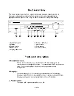
Page 8: ...e button 9 Volume control 5 Display y button Front panel description 1 Headphone Jack Stereo headphones having a standard inch binaural plug can be connected to the headphone output The headphone jack is connected to zone 2 of the preamplifier Use zone 2 when you wish to use headphones 2 Display The AVP display is a 16 character alphanumeric fluorescent display Displays current mode of preamplifie...

Page 9: ...r When used in combination with MENU it will change that options setting In TEST it selects the next channel When used in combination with MODE it selects the next surround mode 7 Menu button Displays a list of menu options used with y x to change the options and settings 8 Enter button Confirms a selection or displays current setting of an option 9 Volume control For controlling system volume Tur...

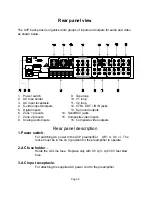
Page 10: ... Surround outputs 6 Zone 1 preouts 14 Send RCV jacks 7 Zone 2 preouts 15 Composite video inputs 8 Analog audio inputs 16 Composite video outputs Rear panel description 1 Power switch For switching AC power to the AVP preamplifier Off O On I The rocker must be in the on I position for the preamplifier to operate 2 AC fuse holder Holds the AC Line fuse Replace only with 0 5 A A 250 V fast blow fuse ...

Page 11: ... Digital the signal must be an Industry Standard Consumer Audio DIGITAL signal into the AVP2030 Laserdisc players normally have an Industry Standard Consumer Audio RF AC 3 signal This type of AC 3 signal requires an AC 3 RF demodulator to be placed between the player and the AVP2030 This converts the RF AC 3 signal out of the laserdisc to an AC 3 DIGITAL signal This signal can then be processed by...

Page 12: ...R 2 V2 OUT Provides a fixed level buffered audio output for sending to a VCR associated with Z2 Connect the V2 OUT on the AVP to the AUDIO IN on the VCR V2 IN Accepts audio output from a VCR Connect the V2 IN on the AVP to the AUDIO OUT on the VCR 12 CTRL OUT Output that allows you to remotely control external devices This output is rated 12 VDC 15 mA continuous The output goes high 12 VDC when th...

Page 13: ...ar right speaker SUB Provides an audio output signal for sending to the input channel of the power amplifier for a passive subwoofer or the input of a powered subwoofer CENTER Provides an audio output signal for sending to the input channel of the power amplifier for the center speaker 14 SEND RCV inputs Not currently used For future applications 15 Composite Video inputs Inputs labeled TV V3 V2 V...

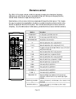
Page 14: ...UT off POWER ON Turns power and CTRL OUT on SYSTEM MUTE Suppresses sound output V1 Selects audio video from component V1 TV V3 Selects audio video from component TV V3 FX Toggles between the standard Direct mode or the last used surround mode V2 Selects audio video from component V2 TAPE Selects audio from component TAPE VLD Selects audio video from component VLD TUNER Selects audio from component...

Page 15: ...enu options use y x to change option settings ENTER Confirms a selection when used while a menu option is displayed displays current setting NUMBERS 0 9 Lets you select an A V preset when followed by ENTER U star Used for advanced operations in conjunction with the numeric key pad 0 9 pound Not used for future applications REVIEW Presents a series of displays showing the current settings repeatedl...

Page 16: ...deo system configuration good preplanning equals great sound Keep these recommendations in mind Keep the cables between audio sources and video sources separate Before you begin connecting equipment decide what types and lengths of interconnects are required for all your components to work well together You should also plan the paths for all interconnects Remember use high quality connections to m...

Page 17: ...e 7 star then 9 then 8 and the display will show The AVP will turn off and back on then it will cycle through the three title messages and then off again The AVP is now reset to factory defaults You can perform this procedure anytime you need to reset the preamplifier to the factory defaults All your presets will be erased Do not interrupt the cycle do not press any buttons on the remote or preamp...

Page 18: ...eft audio output on the CD player then attach the other end to the white left CD audio input on the AVP 2 Attach one end of the audio interconnect cable to the right audio output on the CD player then attach the other end to the red right CD audio input on the AVP Audio Video source The procedure listed is for connecting a DVD VLD player to the AVP analog inputs Use the same instructions for conne...

Page 19: ... AVP 3 Attach one end of the composite video interconnect cable to the video out on the VCR then attach the other end to the yellow video input on the AVP labeled V1 Or use the S video connections The preamplifier will not convert S video to composite or composite to S video This connects the VCR to the AVP for viewing tapes Now complete this procedure to make recordings through the AVP Recordings...

Page 20: ...ax If you wish to use a laserdisc player that has a RF Dolby Digital output you must convert it to digital Dolby Digital The B K DT 1 will do both conversions for you To connect a digital input to the AVP simply connect a coax cable from the digital output on your source CD DVD VLD etc to the appropriate orange digital input on the AVP CD DVD VLD etc In the SETUP menu select digital on for the app...

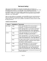
Page 21: ...scription Left Right Large 80 Hz high pass filter off Do not sum bass to subwoofer Full range to front left and right Small 80 Hz high pass filter on Sum bass to subwoofer Filters bass frequencies from front channels and sends it to the subwoofer fc 80 Hz 12 dB Oct Center Large 80 Hz high pass filter off Do not sum bass to subwoofer Full range to center channel Small 80 Hz high pass filter on Sum ...

Page 22: ...front speakers SW Bass Ultra Allows for all channels to be summed to the subwoofer regardless of SMALL LARGE speaker settings Delay settings CTR DELAY Center channel delay The center channel has a variable delay that may be set from 0 ms to 5 ms This adjustment is designed to delay the center channel speaker when the front three speakers are not lined up on the same plane SUR DELAY Surround channe...

Page 23: ... 0 ms Stereo listening mode STEREO F R LF RF LR RR 0 ms Front left is sent to the rear left and SUB front right is sent to the rear right SUB is the front left and right signals summed STEREO HALL LF RF LR RR 0 15 ms Same as 3 STEREO HALL with no SUB or center channel 15 30 ms DIRECT LF RF SUB 0 ms Direct mode is the same as Stereo mode except the 2 channel output signal is pre processor for analo...

Page 24: ...ate by sitting where you normally sit to watch movies or listen to music This is your ideal listening position Once in this position adjust the volume of each channel to match the others You can do this by listening to each speaker and making adjustments Or to verify equal decibel levels dB you can use a sound pressure level meter Do not use calibration to boost or cut a channel For example if you...

Page 25: ... toggle between BASS NORMAL and BASS LFE OFF modes by pressing x or y Press ENTER the display shows You can toggle between SW BASS NORMAL and SW BASS ULTRA modes by pressing x or y Press ENTER the display shows You can increase center delay to 5 ms by pressing the x or decrease back to 0 again by pressing y Press ENTER the display shows You can increase surround delay to 15 mS by pressing the x or...

Page 26: ...etected Dolby Digital surround processing is automatically used Digital AC 3 Selects the corresponding digital input for Dolby Digital Surround Processing PCM signals are not processed in this mode Press ENTER the display shows Press ENTER Press ENTER Press ENTER Press ENTER Press ENTER the display shows You can increase to 6 0 dB by pressing the x or decrease to 6 0 dB by pressing y This holds tr...

Page 27: ...ncrements Equalize the volume level of all the channels by adjusting the calibration of each individual speaker until they all have the same volume from your ideal listening position You can move from channel to channel by pressing the x and y buttons or the ENTER button Press ENTER the display will show Press ENTER Press ENTER Press ENTER Press ENTER Press ENTER Press ENTER the display shows ...

Page 28: ...ncluding the preset name for ease of operation Recall a preset Using the remote control press a number on the keypad to display the preset name Pressing A selects bank A Once you press a preset number you can then press x or y to step through all the preset names If the AVP is off pressing a preset number will turn the preamplifier on then pressing ENTER will select that preset Keypad Display show...

Page 29: ...mode is displayed Next set the desired volume level Now save the preset by pressing SAVE Press 1 Press ENTER to select and overwrite the displayed preset Your settings are now saved under preset 1 any time you select this preset your settings will be recalled Follow the same procedure for the other presets Rename a preset Once you save your own custom preset you can rename it to make it easy to re...

Page 30: ... or y changes the character pressing ENTER accepts or skips the blinking character Continue the steps above until you achieve Pressing ENTER at the last character completes the renaming session and exits The presets are independent for each bank allowing you to save different names in each bank The character set you have available for renaming is shown below A Z 0 9 space You can also rename the s...

Page 31: ...2 you must connect the analog cables from your sources to the preamplifier You can connect the digital and analog cables for the same source to the preamplifier Making your connections in this manner will allow you to use the digital for zone 1 and analog for zone 2 Zone 2 volume can be controlled in different ways as follows 1 Set the remote to ZONE 2 slide switch on side and operate the MASTER V...

Page 32: ...o hear at the time you can select the appropriate preset without having to go through the SETUP menu and surround mode changes again It should be noted that only the DIGITAL ON mode when set in the SETUP menu allows the AVP to automatically switch over to Dolby Digital Surround Processing when a Dolby Digital digital input is detected This automatic feature also provides automatic switching back t...

Page 33: ...ster reset for the preamplifier and will erase everything that was programmed into the system memory Factory reset Reset the AVP before you start Plug in the power and turn the AVP on When the display shows Press the 7 star then 9 then 8 and the display will show The AVP will turn off and back on then it will cycle through the three title messages and then off again The AVP is now reset to factory...

Page 34: ...page 4 Wrong source mode 24 30 selected analog digital 5 Tighten repair or replace 5 Line stage to amp cables cable loose or faulty 6 Tighten repair or replace 6 Source to line stage cables cable loose or faulty Loud hum or buzz on one 1 Poor ground connection in 1 Check all connectors and or more channels interconnect cables repair as necessary Surround sound does not 1 Recordings are not Pro 1 P...

Page 35: ...ar Less than 05 Subwoofer Signal to Noise Ratio 89 dB CCIR 2k Weighted max level Input Impedance 50k Ohms Output Impedance 221 Ohms Noise Test Reference Level 12 5 dB Surround Outputs non inverting 6 Audio Inputs 7 Non inverting audio outputs Zone 1 Audio Outputs extra L R 2 sets Zone 2 Audio Outputs 2 sets Video Specifications Frequency Response 3 3 dB 20 Hz 10 MHz Buffered Input Impedance 75 Ohm...

Page 36: ...nsions width 17 inches height 3 inches depth 12 inches Care and cleaning Under normal use the preamplifier will not require any special care Over time you may wish to clean the exterior of the unit by wiping it with a damp cloth to remove any dirt or dust that accumulates on it Do not let any liquid enter the preamplifier thru the vents in the top cover You may clean the connectors on the back pan...

Page 37: ... liable for any incidental or consequential damage arising out of a defect in material or workmanship of the unit during the terms of this warranty or thereafter Some States do not allow the exclusion or limitation of incidental or consequential damages and the foregoing exclusions may not apply to you This warranty gives you specific legal rights Your may also have other rights which vary from St...

Page 38: ......

Reviews: