background image

B K

&

S

B

IMPLY

ETTER!

45

Input Configuration - Tab 6

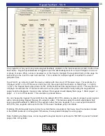
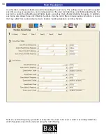
1. Select which Zone Dedicated Input you wish to setup.

2. Video No / Yes:

If “NO” is selected, the CT Receiver will keep the video input selection from the last selected video source. 
If “YES” is selected, the video input selected will change along with the audio input selection.

3. Input Mode:

Mono or Stereo - Select the best mode for the source connected to this Input. When set to mono, the right
and left input signals are summed. 

4. Selection Mode:

Manual or Auto - When using Auto, the CT Receiver will select the source and/or turn the zone on if EITHER
audio or video is sensed at the dedicated source input.  When using auto-sense to detect an input signal, the
CT Receiver will “remember” the previous state of the zone.  Once the dedicated input signal is switched off
the zone will return to its previous state. If desired, the auto-sensing feature may be turned off by selecting
“Manual”.  The dedicated input may be selected at any time using the IR command “D-IN” from the B & K IR
database.

5. Release Time:

Release time dictates how long the the auto-sense feature will wait before releasing the dedicated input (1-
25 seconds or Forever). Use forever (bar to the right) if you don't want the Input to change until the user
manually selects a new input. If the source has a video output, set to 5 seconds or less. If the source has
audio only, use 25 seconds so that a quiet passage in the music will not release the input prematurely.

1

2
3
4

5

3

2

Summary of Contents for CT300.3

Page 1: ...B K Components Ltd User Manual CT600 1 CT600 3 CT300 3 Multi Zone Audio Video Receivers 14067 121206 ...

Page 2: ... names are trade marks or registered trademarks of their respective companies or organizations B K Components Ltd sells its products through authorized dealers Buying from an authorized B K Components Ltd dealer insures that you have a FACTORY WARRANTY on your B K Components Ltd product A warranty on B K Components Ltd products is NOT VALID if the products have been purchased from an unauthorized ...

Page 3: ...ox CD ROM P N 13323 9 Installation and System Diagrams 10 Basic System Hookup 11 Installation Considerations 12 AC Power and Line Fuse 13 Speaker Connections for CT Receiver 13 Shared Source Inputs 14 Dedicated Local Source Inputs 14 Digital Audio Connection 15 Buffered Outputs 15 CT Receiver Speaker Connections 16 Connecting an External Amplifier 17 Composite Video Outputs 18 CK1 2 Keypad Connect...

Page 4: ...roups with Mono Zones 40 Sub Zoning 41 Input Settings Tab 3 42 Power On Titles Tab 4 43 Power On Preferences Tab 5 44 Input Configuration Tab 6 45 Page Event Tab 7 46 Display Tab 8 48 Control Tab 9 49 Security Tab 10 51 RS 232 Communication Tab 11 52 Preset Operation Tab 12 54 Keypad Feedback Tab 13 55 Room Equalization 56 Preset Editor 58 Serial Macro Editor 60 Setup Using the On Screen Display 6...

Page 5: ...ideo System Setup 66 Control Menu Setup 69 Setup Presets 72 Control System Setup 73 System Status 74 Zone Planning Worksheets 75 Troubleshooting Guide 78 Limited Warranty 79 Specifications 80 CT Series A V Control Center 81 Additional Information 82 ...

Page 6: ...B K S B IMPLY ETTER VI THIS PAGE IS INTENTIONALLY LEFT BLANK ...

Page 7: ...er channel into 8 ohm speakers and up to 85 watts per channel while driving 4 ohm speakers In addition CT Receivers may be linked for use in up to 127 zones configurations allowing 9 shared sources all with independent command and control Please visit B K on the web at www bkcomp com for information on our hand assembled product lines includ ing digital preamplifiers receivers and high current pow...

Page 8: ... In each zone the user may select sources raise lower volume adjust bass treble independently without affecting users in other zones The CT Receivers give all the performance and ability that a dedicated stack of high end sepa rates would give a user in each room without any of the visible clutter The receiver and all shared sources may be concealed in a cabinet or rack in one central location The...

Page 9: ...each keypad Each keypad stores its program on an EEPROM so even if the power is lost the memory is still good for up to 10 years Point Any Remote Control at the Keypad The integrated IR pass through sends the commands of any IR remote control to both local installed compo nents and the central system If your client wants to use a remote control in any room they may simply point it at the B K keypa...

Page 10: ...witch is set to ON in which allows the power function of a remote or keypad to power the zones on or off While the unit is in SLEEP the electrical consumption is reduced to about 35 watts CT Receiver Front Panel 4 2 1 Available faceplate options are 17 Black standard 17 Silver 19 Rackmount Black and 19 Rackmount Silver Unit shown is 17 Silver ...

Page 11: ... Video shared Source inputs that may be shared throughout all zones See page 14 6 9 Infrared emitter outputs for IR routing to source pieces 1 8 3 5mm mini jack See page 21 7 Removable four position phoenix speaker connections Speaker connections are 4 ohm stable See page 16 8 6 Zone dedicated Audio Video inputs for local sources one per zone See page 14 9 Link In and Link out for connecting multi...

Page 12: ...al pages of func tions Main Button The Main button always returns to the Main Menu so that a may new device activity or zone may be selected Screen Title Displays what Source is selected i e device or activity like CD or SAT Main indicates the Main Menu for selecting a new device or activity Programming Jack Behind the Faceplate Four tabs hold the faceplate to the keypad chassis To remove the face...

Page 13: ...ntrol to the main unit and components connected to flashers Power LED lights up when this Zone Room is ON Controlled by the 12V Control Up Down and Mute Controls may be programmed for Volume and Mute control for the B K zone or any device Programming Jack Behind the Faceplate Four tabs hold the faceplate to the keypad chassis To remove the faceplate simply pull the faceplate off the keypad chas si...

Page 14: ... into IR view of the keypad in Zone A the 128 Code Set remote will only control Zone A when in Zone A Take that same remote into Zone B and it will only control Zone B MZ 128 BUTTON B K IR FUNCTION B K ALL COMMANDS ON B K POWER ALL B K POWER UP OFF ALL B K POWER OFF VOLUME ALL B K VOLUME UP VOLUME ALL B K VOLUME DOWN 0 ALL B K VOLUME 0DB 2 ALL B K VOLUME 20DB 4 ALL B K VOLUME 40DB 6 ALL B K VOLUME...

Page 15: ...them to the unit The BK CT Series CD includes programming software for B K receivers proces sors the SR10 1 remote control and CK1 2 CK1 1Keypad Editors B K Hardware Quick Tools for CT Receivers and the HD6 and the Flash File Download for updating the HD6 CT 600 1 CT 600 3 and CT 300 3 A PDF library of the B K product line is also included with BK Suite The library includes all B K product manuals...

Page 16: ...es for details describing installation procedures Zone C Keypad Zone B Keypad Zone A Keypad Zone E Speakers Zone A Speakers Zone C Speakers Zone F Speakers Zone Speaker Connections Zone B Speakers Zone D Speakers Zone F Keypad Zone E Keypad Zone D Keypad Composite Video Left Audio Right Audio Positive Negative ...

Page 17: ...ter Basic CT Receiver Keypad System Hookup Zone C Keypad Zone B Keypad Zone A Keypad Zone E Speakers Zone A Speakers Zone C Speakers Zone F Speakers Zone Speaker Connections Zone B Speakers Zone D Speakers Zone F Keypad Zone E Keypad Zone D Keypad Composite Video Left Audio Right Audio Positive Negative Zone F Monitor Zone C Monitor Zone B Monitor Zone A Monitor Zone E Monitor Zone D Monitor ...

Page 18: ...ension cord Speaker wires tied together and attached to the cabinet rack on the opposite side of AC Power lines Antennas should be routed so that they may be re positioned later IR emitters should be routed and tied down but NOT attached to source components Remember emitter position is best done with the system powered up Emitter wires may safely be run adjacent to AC Power cables Combine Keypad ...

Page 19: ...g on the receiver using the main power button the front panel LED should now be lighted After 45 seconds the receiver has finished it s boot process Turn off the main power but ton and disconnect the AC power cord Connect all A V and other interconnect cables and re connect the AC power cord The CT Receiver connection process should now be complete Checking the AC Power fuse 1 Power off the unit a...

Page 20: ...y to that individual zone Typically this feature is appropriate for sources that are physically located in the zone such as DVD players or satellite boxes in bedrooms or dens By running well shielded audio and video cable from the local source back to the CT Receiver the user may utilize the auto sense capability which is built into these inputs The CT Receiver will immediately auto detect the aud...

Page 21: ...tween other whole house units or home theater systems When video is not needed to be routed the CT Receiver composite video inputs outputs may be used to route coax digital audio Simply connect the digital coax connection from the source device into the shared or dedi cated video inputs The CT zone video outputs will now switch digital audio to a surround processor Source Ref 50 S2 Note When setti...

Page 22: ...e A Speakers Zone C Speakers Zone F Speakers Zone Speaker Connections Zone E Speakers Zone D Speakers Positive Negative R Right Positive Speaker Output Red Wire R Right Negative Speaker Output Green Wire L Left Positive Speaker Output Red Wire L Left Negative Speaker Output Green Wire Negative Speaker Input Green Wire Positive Speaker Input Red Wire ...

Page 23: ...ume control is needed for line level fixed appli cations Connecting an External Amplifier An internal jumper is used to change the zone RCA outputs between line level fixed or variable This configu ration is most beneficial when a zone is to be used with additional external amplification Open the chassis and locate the blue jumper on the audio card for the Zone Line Outputs The jumpers are in line...

Page 24: ...posite video output The video signal will shut off when the zone is shut off Composite Video Outputs Zone F Monitor Zone C Monitor Zone B Monitor Zone A Monitor Zone E Monitor Zone D Monitor Menu System To access the menu make sure you have a monitor coming from the zone A video out Then push MENU on the MZ 128 remote Use the UP DOWN LEFT RIGHT and SEL buttons in the center of the remote along wit...

Page 25: ...unless routing is set to ALL and the main CT microprocessor for B K commands CTRL OUT The 12VDC 200mA outputs are used to control external amplifiers relays screens or devices that activate when a volt age is detected The default action is that the voltage is ON when the Zone is ON OFF when the zone is off This is controlled by going into the Advanced FULL Setup Tab 9 in BK Suite The 12VDC control...

Page 26: ...ommon in many homes you may opt to expand a zone to include several rooms Many keypads may be connected in a daisy chain from the master keypad in that zone The master is the keypad which is home run back to the CT Receiver To daisy chain keypads simply connect a straight through CAT 5 cable terminated into RJ 45 between the two keypads All the chained keypads need be pro grammed separately Daisy ...

Page 27: ...r all Emitter output more consistent levels when connected in series Parallel connections may work some of the time Series connections are recom mended for consistent operation Standard 2 conductor 16 gauge speaker wire is ideal for long runs from the keypad to a Local TV or device using an IR emitter Utilizing CAT 5 cable will also work well IR Emitter Outputs Each of the nine shared sources may ...

Page 28: ...ra is connected to The user may specify which zones should or should not respond to either or both Page Events see Page Event expla nation on page 47 The diagram below illustrates the installation of a front door security camera coupled with a doorbell By default Page Event 1 switches to input 8 when a voltage is detected through Common Control 1 IN and IN Also Page Event 2 switches to input 9 whe...

Page 29: ...eo output RESET is located in the Memory Backup restore option Using a IR control device in Zone A press menu 5 left enter A factory reset takes approximately 60 seconds to execute Factory Reset On a CT 600 3 600 1 300 3 through Quick Tools Connect to the B K Quick Tools software available on www bkcomp com Select the appropriate baud rate and com port then click on Com Start appropriate IP addres...

Page 30: ...CT system interface Typically only one form is used however all may be used in more advanced systems RS 232 or Ethernet greatly enhance the com mand and control of the CT system controller when combined with the advanced features such as Serial Macros If user interfaces primarily communicate and control the system with IR link multiple CT Receivers with the IR Link In and Out If user interfaces co...

Page 31: ... CT Receivers are linked together All flashers going to source pieces would be connected using the 1 8 mini jack Flasher Outs IR Outputs 1 through 9 on the FIRST CT Receiver like shown Note The LINK IN LINK OUT is for IR only Audio and video signals still need to be connected using the buffered inputs and outputs See Page 15 for more information CT 3 CT 2 CT 1 Along with the RJ 45 Link In and Out ...

Page 32: ...the system the theater becomes a CT zone IR Code sets work consistently with the home theater line as they do with the CT line Code set 001 is used for zone 1 code set 002 is used for zone 2 The following depicts the communication between CT and Home Theater products Adding Home Theater Products Adding a Home Theater Back of AV40DP breakout box RJ 45 side Front of AV40DP breakout box RCA side From...

Page 33: ...able At power up the HD6 will learn all of it s settings from the CT Receiver No additional HD6 setup is required The LINKING process takes about 15 seconds When connected in this manner the HD6 will stay in sync with the CT Receiver for keypad and IR messages Dedicated input and page event settings that depend on video detection will continue to work as expected even though the video is connected...

Page 34: ... K Tool Suite includes software for setting up B K Receivers Preamplifiers SR10 1 remote and CK1 2 CK 1 1 Keypads B K Hardware Quick Tools is a RS 232 test software for troubleshooting with the HD6 and CT Receivers The Flash Download Update is the program used to update the software in the HD6 CT 600 3 CT 600 1 and CT 300 3 The installation path for BK Suite is c program files B K Components Lt BK...

Page 35: ...45 Black CT Receiver Connection Plug one end of a RJ 45 terminated CAT 5 cable into the main RS 232 communi cations port on the back of the CT Receiver Serial Connection Plug one end of a RJ 45 terminated straight through CAT 5 cable into the serial communications port on the back of the computer using the serial DB 9 to RJ 45 Adapter Plug the other end of the RJ 45 terminated cable into the RS 23...

Page 36: ...at all setup be done virtually to avoid system errors Once the setup files have been created connect to the unit and open the saved files Typical PC setup should follow the described procedure 1 DO NOT CONNECT UNIT TO COMPUTER This is considered virtual mode Open BK Suite A V Setup from BKTask 2 When Tool Suite is first opened the Device Investigator automatically scans to find a connected B K pro...

Page 37: ...tion will be established 7 Once a live connection has been established open the file previously created Once the file is opened it will overwrite the settings in the B K product with the settings configured in the setup file Note While a live connection is established with a CT Receiver any changes made in BK Suite will immediately update inside the unit itself The system file should be saved on y...

Page 38: ...ets Open the Advanced System Editor to program all of the fun damental parameters of your CT Receiver system Select another B K Virtual Product to setup Run the Device Investigator so that you may connect to the CT Receiver and upload your setup files Use the Serial Macro Editor to to con trol or communicate with a RS 232 capable device B K Keypads etc Get information about your current connection...

Page 39: ...ones configure power on preferences and name sources When a file is saved to the PC in the Basic Menu both a txt and csv file are created in the same directory These files create keypad button layout templates based off the locations of the devices assigned in Tab 2 These files may be used as a reference when creating keypad files in the keypad editor See Next Page The following figure details how...

Page 40: ...set up a keypad for RS 232 feedback synchronization Tab 2 tells the CT Receiver where devices are located on the keypad so the zone input syncing will operate properly Match each input with the it s corresponding location on the keypad Basic Setup Keypad Feedback ...

Page 41: ...within the CT Receiver Setup should proceed in the numerical order of the tabs Remember it is always best to save frequently Typically choose to save settings with the cus tomer s last name and a data or revision number It is usually best to save all of your files in one directory The default directory is C Program Files B K Components Ltd BK Suite Advanced Full Setup BK Suite should be updated re...

Page 42: ...djust the set tings of 2 You may set Zone A to stereo or mono as required When stereo is selected the form will appear as shown to the left If mono is chosen the Zone A form will change its appearance to the mono ver sion as shown to the left The form displays new choices for the split mono zone The right or left side may con figured fixed or variable or may have vol ume limits set The changes mad...

Page 43: ...s for Mono Zones This setting dictates the configuration for the amplifier The Variable assignment will allow speakers connected to the Zone Speaker Outputs to be controlled using an IR keypad or remote control Selecting the Fixed assignment is available for external rotary type volume controls This fixed or variable selection is applicable to the amp channels only It does not apply to the line le...

Page 44: ...1 to 036 to the third and so on 3 Title Name the group zone with a name that will make sense to the client If the group controls just one zone name it for that zone If it will control several zones name it intuitively for the area it controls 4 Hardware Zones Work by row check the boxes for zones that will make up each group In the fig ure above code 0 1 7 has been assigned to control zones A B an...

Page 45: ...atures by utilizing discrete Code Sets to enable any keypad to control any zone any group of zones or the whole house B K created 128 different sets of the same CT Receiver commands These commands will also work with B K home theater units assigned to the same code set The primary commands are as follows Each code set differs from the next only in the initial IR code identification or prefix i e 1...

Page 46: ...to control both sides together Check the desired side of the zone corresponding to the Code Set it will be controlled by Regardless of how this is set this split mono zone will always listen to the same input When the input is changed for one side of the mono zone the input will be changed for the other side as well Bass treble and EQ settings will be shared between the split mono zone at the same...

Page 47: ...one must listen to the same source but volume and on off states are independent via the two keypads The key pads are daisy chained to the same zone control terminal The CT Receiver must be setup to respond to the discrete Code Set for each mono zone Furthermore the corresponding Code Set should be pro grammed onto the keypad Thus the Master Bath keypad will affect only the Master Bath and the Mast...

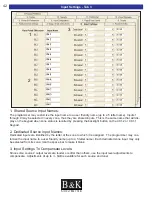
Page 48: ...tton on the CK1 2 or CK1 1 Keypad 2 Dedicated Source Input Names Dedicated inputs are identified by the letter of the zone to which it is assigned The programmer may cus tomize the input name to a user friendly name up to a 5 letter name Each dedicated zone input may only be selected from its zone Use the space bar to make it blank 3 Input Settings To Compensate Levels Since some sources output le...

Page 49: ...B K S B IMPLY ETTER 43 Power On Titles Tab 4 Power On Titles are not available on the CT 600 3 600 1 and 300 3 ...

Page 50: ...ct Power On Setting Set the Power On Preferences for the Audio Input Video Input Volume Bass Treble Equalization AM Frequency FM Frequency and or FM Stereo mode 3 Last Used When powered on the zone or group of zones will return to its last used state For example if the audio input was set to In 1 when powered off the zone will power on with the audio from In 1 4 Power On Preference The zone or gro...

Page 51: ...ource input When using auto sense to detect an input signal the CT Receiver will remember the previous state of the zone Once the dedicated input signal is switched off the zone will return to its previous state If desired the auto sensing feature may be turned off by selecting Manual The dedicated input may be selected at any time using the IR command D IN from the B K IR database 5 Release Time ...

Page 52: ...both Page Events Page Event 1 will switch to input 8 Page Event 2 will switch to input 9 However you may override this in the Zone Page Event selection box shown below 2 Activated By Select the desired application to determine when the Event is ACTIVE If you select Audio or Video Sensing an audio or video signal present in the selected input will trigger the Page Event If Common Control is selecte...

Page 53: ... the time the voltage is dropped Use Forever slide bar all the way to the right if you don t want the event to end until the user manually selects a new input or a new volume setting If audio video sensing is used adjusting the delay will affect how long the CT Receiver will wait once the signal is lost 5 Page Event Affects Control Out and Flasher Outputs Yes When the event activates the flasher o...

Page 54: ...B K S B IMPLY ETTER 48 Display Tab 8 Front Panel Display is not available on the CT 600 3 600 1 and 300 3 ...

Page 55: ...ar zone is on and turns off when the zone is off Default Setting Zone Active The Control Out will turn on only if the zone is on AND the CT Receiver may detect an audio or video signal on the input the zone has selected Zone Off The Control Out will turn on only if the zone is off Selected Input The Control Out is on only if the zone is on and this input is selected switched to by the user Note th...

Page 56: ...l route from the keypad terminal to the IR output for only the input that is selected for that zone This allows identical source components to be used independently in the system Default Setting All Inputs If simultaneous flashing is desired set to All Inputs Any IR data received from the keypad control terminals or All IR In connection will be sent to all 9 IR outputs Off All 9 IR outputs will be...

Page 57: ...ced Unlock Security Settings via an IR Button Press Should there be a need to make adjustments to the CT Receiver without a PC and the CT Receiver has locked or hidden menus there is a simple procedure to unlock and edit the security settings To unlock the advanced security settings 1 Cold boot the unit main power switch set to off then on 2 Wait 12 seconds for the initial power up sequence to fin...

Page 58: ...S 232 protocol allows B K product to listen receive ID or talk transmit ID to other B K products The pro grammer need to change the identifier when external automation system to control more than one B K prod ucts is used For instance if you wanted to send a Reference 50 preamplifier an IR triggered RS 232 macro to power off the Reference 50 from a CT Receiver you should set the Transmit ID of the...

Page 59: ...x value 60 volume 0dB All Both Outputs both BKC DIP Update and BKC DIP Reply message 7 V2 0 Enabled Allows for more advanced BKC DIP control of the Receivers including preset parameters 8 Convert IR to BKC DIP Messages When enabled the CT Receiver will convert and repeat the B K IR commands into RS 232 The RS 232 message is repeated out to the RS 232 I O RJ 45 This may be used for a system with B ...

Page 60: ...preset name manually or retain the previous name 3 Favorite Preset Recall Favorite presets are accessed by using the B K s Channel Up and Channel Down Commands There are two modes of operation If it is set to Enter Button Required then the user is required to tap the Enter button to recall the preset after the user taps on Channel Up and or Down The second option is Automatically Recall Automatica...

Page 61: ...ay the the CD player is selected the CT Receiver will send out the jump command correctly telling the keypad what page should be displayed Keypad Jump defines if the keypad should display Main page 1 Main page 2 or page 1 2 3 or 4 of that device This example is pictured above Do not change the Keypad Transmit ID from the default 255 FFh unless you plan to program every keypad with a corresponding ...

Page 62: ...ings for each zone The settings made here will be applied each time a zone is powered on and is independent of the user controlled bass and treble adjustments For each zone setup the default bass and treble levels as well as their affected shelving frequency In addition each zone also allows three notch filtering functions Use the notch filters to make audio corrections in zones that may suffer fr...

Page 63: ...de in dB of these enhanced lower frequencies Typically a room will have 3 large peaks due to the distance between the front back walls left right walls and the floor ceiling B K provides 3 notch filters to address each of these peaks Zone Notch Gain The level of decrease in dB level for the notch frequency and width Zone Notch Frequency The frequency that will be affected at the lowest point of th...

Page 64: ...he Edit Preset tab on BK Suite In virtual mode the presets will default presets will be displayed on the preset editor table If editing the presets while connected to the CT Receiver the preset editor will interrogate the unit for the cur rent preset settings The current internal presets will be displayed once a live connection is established When the presets are edited save to file by going up to...

Page 65: ... type in the desired frequency 5 Zone Favorites Once all of other parameters have been set it must be decided which zone s the preset is to be made available in Zone Favorite are used to define what presets are available in which zones By checking a zone s the preset configured will be available for use in that zone s when using the Channel and Channel commands for that zone Example If you do not ...

Page 66: ...r go to the B K support section of our website at www bkcomp com Below is a simple example using the Serial Macro Editor to trigger the zone status feedback when a zone powers on This example may be used on a default CK1 2 keypad Select a macro in the serial macro edi tor Choose the BK Code set 128 Choose the IR command Power On 40h from BK Data this will be the trigger Create the RS 232 string FF...

Page 67: ... straightforward as using a PC and BK Suite Nevertheless it is often convenient to touch up one or two parameters of the system using the on screen or front panel menus All on screen setup on a CT Receiver must be done through the zone A video output run to a monitor accessed by remote control Remote control access to the on screen menu is limited to zone A only The on screen menu may not be acces...

Page 68: ...screen will exit the menu system At any time the menu s may be exited completely by pressing the EXIT button note when changing settings pressing exit may not completely allow an adjust ment it is recommended to press Menu until the menu system is completely exited Tapping the MENU button on the remote control brings up the On Screen MAIN MENU Use the Up and Down arrows to navigate to the sub menu...

Page 69: ...ss 12dB Freq 103 3 Treble 12dB EQ OFF next item adjust 0 9 10 recall preset SAVE MENU main menu Zone 0 WHOLE HOUSE FAVORITE PRESETS Preset 0 Yes Our Favorite 0 9 10 preset rename SEL next item adjust MENU main menu SETUP AUDIO VIDEO SYSTEM 1 Inputs 2 Zones 3 Power On Settings 4 Page Event 5 Zone Sync 6 Room Equalization next item SEL select MENU main menu SETUP CONTROL SYSTEM 1 Zone Code Sets Name...

Page 70: ...the choice displayed press the EXIT or MENU button accordingly to navigate or exit the menu system The On Screen Display Menu will read As in the example above the single line displays are often abbreviated to fit the menu information Thus Audio Video System Setup becomes A V Setup etc Tip For a complete setup B K suggests you use in the order of ease of use 1 BK Suite 2 On Screen Display Setup If...

Page 71: ... configure the set tings then press SAVE and then the preset number to be saved For example to save preset 11 press SAVE 10 1 Zone Operation Zone Operation Menu Once in the Zone Operation Menu current zone parameters may be adjusted As these parameters are adjusted they affect the zone that is selected in this example zone A code set 0 1 1 If you keep pressing the Left Right adjust buttons you wil...

Page 72: ...enu button will return you to this menu Inputs Sub Menu Select one of the nine shared inputs or the 6 dedicated zone inputs Then do the following steps 1 Name the input 2 If needed adjust the level to match other inputs 3 Select Stereo or Mono 4 Select Yes or No for video If you select NO the CT Receiver will remain on the last used video source when that input is selected Naming an Input Select L...

Page 73: ...l Set to VARIABLE for standard adjustable volume via keypads and remote con trols Set to FIXED if this zone uses impedance matching volume controls for background music or if you desire it be set to a fixed output level This is for amplified outputs only 5 Max Level Set this to the maximum level the zone is to be able to achieve if the output it set to variable If set to fixed this will be the out...

Page 74: ...st and use Left Right to adjust the item selected The zone may switch to any shared input change volume or mute volume etc Note Only Zones which have been setup under the Zone s Menu to respond to Page Event 1 or 2 or Both will be affected by the Setup Page Event screen Page Events are described on page 45 Use Left Right to select which group of zones to set up Then use up down to select changes U...

Page 75: ...ric keys to aid in the naming process 1 ABC 2 DEF etc Control System Menu Control Menu Setup From the Setup Control Menu use the Up Down to highlight a sub menu Select by pressing SEL or ENTER Setup Zone Room Equalization First select which of the six zones you want to configure Adjust Treble and Bass frequencies and level using the Left and Right functions on the remote and Up Down to move to the...

Page 76: ... zone to include Left Right or Left Right When additional hardware zones are included they are all controlled by the code set in this case code 017 Zone Control I O Use the Left Right keys to select the zone Use the Up Down keys to select the setting to adjust Use the Left Right keys to pick from the available options Control Out will determine when the 12VDC 200mA control volt age is sent for eac...

Page 77: ...ses No IR data will transmit out the 9 IR outputs Control System Menu Common Control I O The CT600 3 and 600 1 are equipped with two 12VDC 200mA common control voltages the CT300 3 is equipped with one This menu setting assign operation to the OUT located in the common control section on the back panel of the CT Receiver They are programmed at the factory to turn on when any Zone is powered on To ...

Page 78: ... not required for the preset to be recalled If set to YES when using B K Channel Up and Channel Down buttons the ENTER button is required for the preset to be recalled Note ENTER must be pressed after a preset is numeri cally selected Security Options Use the Up Down to select a security setting to configure Then use the Left Right keys to select from one of the available options Setup Menu Visibl...

Page 79: ... B K product only that unit will be controlled This is useful if several B K prod ucts are interconnected for other purposes YES Default Enables all RS 232 commands to be transmitted out the zones port NO Only disables only auto BKC DIP commands from being transmitted out the zones port Note Macro strings Serial and Keypad feedback information will still be transmitted out the zones port When Memo...

Page 80: ...and control in out activity Unit Information The Unit information screen gives factory information that is useful for both the end user and B K technical support including model serial number and software version Audio Status The Audio status screen enables you to view power state input tuner frequency volume balance bass treble and EQ settings for all zones is an indicator for FM in Stereo A V De...

Page 81: ...Yes No Yes No Yes No Name of Zone How Many Keypads Master Slave 1 Slave 2 Slave 3 Zone TV Stereo Mono Number of Speakers External Amplifier Line Level Output If Fixed of Volume Controls Dedicated Source Nameonthe Keypad LocalSource Controlfromthe keypad ofEmitters Total Number of Keypads Total Number of Volume Controls Variable Fixed Variable Fixed Variable Fixed Variable Fixed Variable Fixed Vari...

Page 82: ...7 IN 8 IN 9 Yes Shared No Yes Identical No Yes Shared No Yes Identical No Yes Shared No Yes Identical No Yes Shared No Yes Identical No Yes Shared No Yes Identical No Yes Shared No Yes Identical No Yes Shared No Yes Identical No Yes Shared No Yes Identical No Yes Shared No Yes Identical No Additional Cables for Home Theater or Local TV s and Components Source Distance for Home Run Total ...

Page 83: ...ager Date ZONE A B C D E F 1 2 3 4 5 6 7 8 9 10 NAME Zone Power On Preferences Preset Radio Stations AUDIO FROM VIDEO FROM VOLUME RADIO FREQUENCY Last Used Last Used Last Used FM Last Used Last Used Last Used FM Last Used Last Used Last Used FM Last Used Last Used Last Used FM Last Used Last Used Last Used FM AM AM AM AM AM AM B K S B IMPLY ETTER ...

Page 84: ...l windows and prompt to return to the Control Panel At that point you may close the Control Panel 7 Disable any and all power management services including any Universal Power Supplies UPS 8 Disable any palm computer PDA syncing software and services such as Hot Sync Manager Pam Sync Clie Connect etc 9 Disable other RS 232 Serial protocol programs that may be using the COM port I e CK1 2 Keypad Ed...

Page 85: ...consistently offer software and hardware upgrades to its processing of audio signals Through upgrades B K delivers exceptional value to its customers But what is Upgradability Upgradability is not a guarantee we define it as a philosophy of design ing and manufacturing products so that as audio technology evolves B K can provide enhancements and improvements to its products that are economically v...

Page 86: ...d 75W 75W 75W Dedicated Zone AV Inputs 6 RCA 3 RCA 6 RCA Zone Line AV Outputs 6 RCA 3 RCA 6 RCA Source IR Flasher Outputs 9 1 8 plug 9 1 8 plug 9 1 8 plug IR flasher voltage 5V with 475W in series 5V with 475W in series 5V with 475W in series Command and Control IR RS 232 Ethernet pending IR RS 232 Ethernet pending IR RS 232 Ethernet pending IR In 1 1 8 plug 1 1 8 plug 1 1 8 plug IR Pass 1 1 8 plu...

Page 87: ...tuitive software suite and a computer This allows fast easy system configuration backup and database archiving Command and Control of multiple CT Receivers inked via RS 232 and IR Link In Out Expansion to 6 zones of High Definition Video when linked to the HD6 video transcoding switcher All B K products sold through authorized dealers are covered by a 5 year parts and labor factory warranty ADDITI...

Page 88: ...ents Ltd SHALL NOT BE LIABLE FOR OPERATIONAL TECHNICAL OR EDITORIAL ERRORS OMISSIONS MADE IN THIS MANUAL The information in this manual may be subject to change without prior notice The information in this manual may be subject to change without prior notice PC requirements 128MB RAM Pentium grade or better processor Windows XP is the recommended operating system Exception BK Suite not supported o...

Reviews: