B K
&
S
B
IMPLY
ETTER!
50
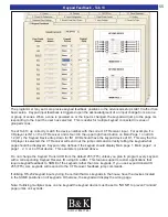
Control - Tab 9
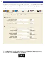
3.Zone Rear Data In Setting:
Allows the IR data input port for each zone control terminal to be switched off. When set to OFF, any key-
pads or IR sensors connected to the back panel the CT Receiver will be rendered inoperable because no IR
will be allowed to pass through the IR data input for the selected zone.
4. Zone Page/Event Selection:
Please see page 45 for Page/Event configurations.
5.Flasher Outputs:
Selected Input - If IR routing is desired, set the Flasher Outputs to Selected Input. When IR routing
is enabled, IR will route from the keypad terminal to the IR output for only the input that is selected
for that zone. This allows identical source components to be used independently in the system.
(Default Setting)
All Inputs - If simultaneous flashing is desired set to All Inputs. Any IR data received from the keypad
control terminals or ‘All IR In’ connection will be sent to all 9 IR outputs.
Off - All 9 IR outputs will be turned off.
6.Rear Panel IR to Flasher Outputs:
Configure the unit as to whether the minijack ‘IR IN’ will pass IR to the 9 flasher outputs. Only the sources
that are selected in a zone will pass through the Flasher Outputs. For example, if zone A is on In 3 and zone
B on In 6 with the other zones powered off, IR will be sent from Flasher Outputs 3 and 6.
3
4
5
6


