B K
&
S
B
IMPLY
ETTER!
71
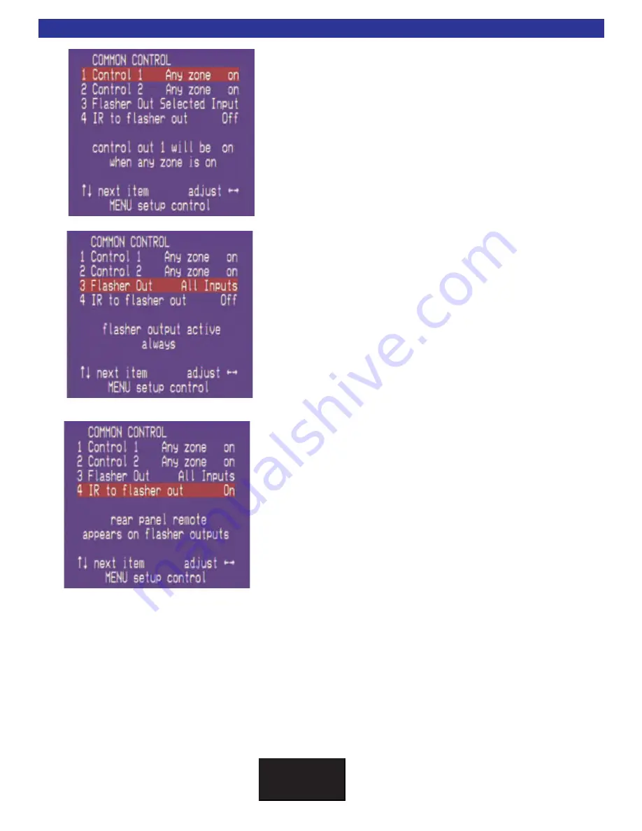
Flasher Out
Below are the three possible choices for the 9 IR outputs:
Selected Input
- IR commands are routed from the keypad ter-
minal to the corresponding IR output for only the input that is
selected for that zone. This allows identical source components
to be used independently in the system. (Default Configuration)
All Inputs
- All flash / simultaneous flash. IR commands from
any zone are routed to all flashers regardless of what input the
zone(s) is on.
Off
- All flashers may be turned off for troubleshooting pur-
poses. No IR data will transmit out the 9 IR outputs.
Control System Menu
Common Control I/O
The CT600.3 and 600.1 are equipped with two 12VDC 200mA
common control voltages (the CT300.3 is equipped with one).
This menu setting assign operation to the “OUT” located in the
common control section on the back panel of the CT Receiver.
They are programmed at the factory to turn on when any Zone
is powered on.
To change this setting use the Up/Down keys to select the
Control Out you wish to program. Use the Left/Right keys to
pick from the available options.Specific options for the common
control settings may be found on page 48.
Rear Panel IR to Flasher Out
This setting configured whether the minijack ‘IR IN’ will pass IR
to the 9 flasher outputs.


