7
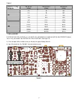
Table 1
Resistive Loading
Examples
R
c desired
(Ohms)
R
i calculated
(Ohms)
R
i standard
(Ohms)
25 30 30.1
45 68 68.1
75 171 169
100 403 402
MC
125
2.1 k
2.10 k
5.0 k
5.3 k
5.36 k
20.0 k
25.0 k
24.9 k
35.0 k
53.8 k
53.6 k
50.0 k
100.0 k
* 100 k
MM
75.0 k
300.0 k
301 k
* Factory Installed
2.
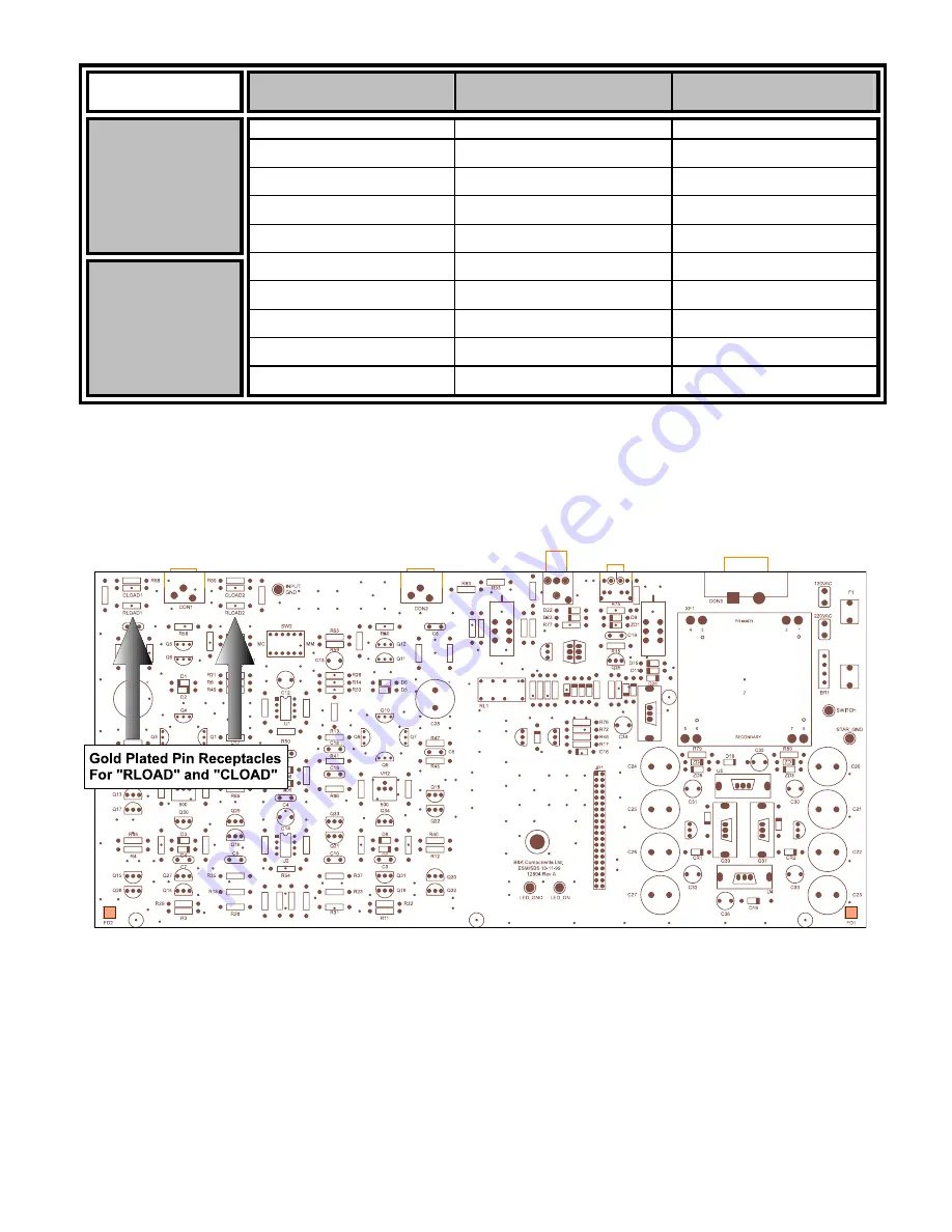
With the front of the unit facing you, locate the two gold plated pin receptacles with the label “RLOAD” between
them. They are located near the back left of the circuit board. (See Figure 3)
3.
Trim the leads of the resistors (one per channel) to approximately 3/8 inch.
4.
Insert the leads into the “RLOAD” pin receptacles securely.
Figure 3


