background image

SAFETY PRECAUTIONS


PLEASE READ BEFORE INSTALLING

WARNING: to prevent fire or shock hazard, do not expose this unit to rain or moisture. Care should be taken to
prevent objects or liquid from entering the enclosure. Never handle the power cord with wet hands.

The lightning flash with arrowhead, within an equilateral triangle, is intended to alert the user of the presence of
uninsulated “dangerous voltage” within the product’s enclosure that may constitute a risk of electric shock to you.

The exclamation point within an equilateral triangle is intended to alert the user of the presence of important
operating and maintenance (servicing) instructions in the literature accompanying the unit.

Caution: To prevent the risk of electric shock, do not remove cover. No user-serviceable parts inside

. Refer

servicing to qualified service personnel.

If an outdoor antenna is connected to the antenna input, be sure it is grounded to provide some protection against
voltage surges and built up static charges. Keep the outdoor antenna away from power lines.


Unplug the Preamplifier Tuner from the AC outlet when plugging in or unplugging cables, when left unused for an
extended period of time, moving the Preamplifier Tuner, or when you suspect lightning in your area.

Prevent damage to the power cord. Do not bend, pull, place objects on, alter, etc. Replace the power cord if it
becomes damaged. Always grasp the plug on the power cord when plugging in or unplugging the Preamplifier
Tuner from the AC outlet.

Your system may produce sound levels capable of causing permanent hearing loss. Do not operate for extended
periods of time at high volume levels.

Make sure the Preamplifier Tuner is placed on a level surface.

Protect the Preamplifier Tuner from impact. (Do not drop it!!!)

The Preamplifier Tuner is equipped with raised feet to provide ventilation, reduce acoustic feedback, and provide
protection against scratching the surface the unit is resting on. We advise against removing or altering feet.

Do not stack anything on top of the Preamplifier Tuner (amplifier, source, etc.) Leave a minimum of 3” clearance
from the top of the Preamplifier Tuner to the next shelf (or component).

The Preamplifier Tuner should be located away from heat sources such as heaters or amplifiers.

Do not perform any internal modifications to the Preamplifier Tuner.

Always connect the Preamplifier Tuner’s power cord to an unswitched AC outlet for normal operation. 

If young children are present, adult supervision should be provided until the children are capable of following all
rules for safe operation.

Do not plug the Preamplifier Tuner’s power cord into an outlet with an unreasonable number of other devices. Be
careful if using extension cords and ensure the total power used by all devices does not exceed the power rating
(watts/amperes) of the extension cord. Excessive loads may cause the insulation on the cord to heat and possibly
melt.

Mistaking 

CONTROL OUTPUT

 or 

IR INPUT

 connectors for audio inputs or outputs may damage your Preamplifier

Tuner or other components.

Damage can occur to your speakers if the power rating of each individual driver is exceeded by the power
amplifiers connected to the Preamplifier Tuner. Ensure that all the drivers in your system are capable of handling
not only the average power being delivered by the power amplifier, but also the peak power that is likely to be
generated during strong passages.


If you are unsure of your speaker power rating, contact the speaker

manufacturer or the dealer where you purchased them.

The Preamplifier Tuner should be serviced by qualified personnel when:

The Preamplifier Tuner is not functioning properly.
The Preamplifier Tuner was exposed to rain or other type of moisture.
The Preamplifier Tuner was dropped, or the chassis is damaged.

1

P/N 13010 REV 0005

CAUTION

R I S K   O F   E L E C T R I C   S H O C K

D O   N O T   O P E N

Summary of Contents for PT 3 series II

Page 1: ...PT 3 series II Preamplifier Tuner Owner s Manual P N 13010 REV 0005...

Page 2: ...P N 13010 REV 0005...

Page 3: ...Volume 21 Preset Operation Setup 20 Source Levels Setup 20 Source Names Setup 19 Favorite Preset Setup 19 Setup 18 Product Info 18 Help 18 Headphone ON 17 Menu 16 Presets 15 Tuner Operation 14 Loudnes...

Page 4: ...ventilation reduce acoustic feedback and provide protection against scratching the surface the unit is resting on We advise against removing or altering feet Do not stack anything on top of the Pream...

Page 5: ...derate listening levels Bass may be used to adjust room equalization Treble may be used to adjust room equalization Customized input and Preset names assign names to presets inputs or the turn on mess...

Page 6: ...gnal for increased clarity and intelligibility at low listening levels Sources your Preamplifier Tuner can directly provide audio from its built in AM FM tuner Typically you will want to connect a num...

Page 7: ...3 Display The Preamplifier Tuner display is a 16 character alphanumeric fluorescent display Displays current status of the Preamplifier Tuner and any changes being performed 4 Volume control For cont...

Page 8: ...dio above 80 Hz to source the SUB output 7 HIGH PASS outputs Variable level outputs for driving external power amplifiers or powered speakers These outputs have been processed through a high pass filt...

Page 9: ...ner includes an IR remote control 6 P N 13010 REV 0005 SEL 2 3 5 6 8 0 9 E 1 BAND ST M 4 7 10 MENU MODE A TV DVD SAT V2 MUTE ON VOL C D V1 TAPE TUNER BAL L BAL R TUNE BASS TREBLE B K REMOTE CONTROLLER...

Page 10: ...o reprogram the source name that will appear on your Preamplifier Tuner s front panel See SETUP SOURCE NAMES y Also note the length of the cable for each component s connection and describe how it sho...

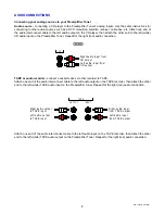
Page 11: ...te deck or other recorder to TAPE Attach one end of the audio interconnect cable to the left audio output on the TAPE recorder then attach the other end to the left white TAPE audio input on the Pream...

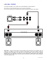
Page 12: ...amplifier you will need to purchase an external B K or other power amplifier Connect the Preamplifier Tuner s SUB output to the audio input of the external amplifier Connect the external amplifier s s...

Page 13: ...chase an external B K or other power amplifier Connect the Preamplifier Tuner s SUB output to the audio input of the external amplifier Connect the external amplifier s speaker output to your subwoofe...

Page 14: ...or powered sub woofers in an audio zone Note The control outputs can output a maximum of 50 mA Check to see that the source you are connecting to the control out requires 50 mA or less current WARNING...

Page 15: ...t in use Sleep mode keeps a bare minimum of functions running in order to allow remote control operation and fast start up Note that the front panel SLEEP button is lit while your Preamplifier Tuner i...

Page 16: ...ds while Preamplifier Tuner analyzes selected source select desired source or TUNER source will appear on TAPE output SOURCE step to source desired source Action From Front Panel From Remote HEADPHONE...

Page 17: ...12 dB 66 adjust bass up or down LEVEL step to BASS then use VOLUME KNOB BASS or BASS Action From Front Panel From Remote ADJUSTING TREBLE Treble increase or decrease the high frequency content in 2 d...

Page 18: ...better one step above or below the frequency that SEEK has found In weak signal areas the tuner may continue to seek all the way to the end of the band To stop this simply press the opposite TUNE butt...

Page 19: ...presets are not limited to Tuner stations You can save custom settings for any source A convenient set of 10 presets come preprogrammed with your Preamplifier Tuner Recalling a Preset FG GE 5 1 35 6...

Page 20: ...om the menu system UP DOWN ARROWS Once you are in the menu system use the TUNE TUNE ARROWS to move to the desired menu selection SELECT remote or ENTER remote or front panel Some menu selections cause...

Page 21: ...he basic menu operations described herein The guide will automatically scroll through each line 3 exit menu system PRESET and ENTER MENU 5 return to main menu PRESET and ENTER MENU 4 display help guid...

Page 22: ...feature allows for skipping selected presets when pressing the remote Preset buttons or front panel preset button When you save a preset it will be automatically added to the favorite preset list ret...

Page 23: ...etup menu TUNE or TUNE From setup menu or 1 Action From Front Panel From Remote Source Levels Setup This setup allows you to match the levels of your sources so that there are no large changes in volu...

Page 24: ...preset volume From preset operation menu TUNE or TUNE From preset operation menu or 1 Action From Front Panel From Remote Preset Naming Your Preamplifier Tuner can automatically generate a preset name...

Page 25: ...7 216 83 0 025 6 72 21 50 return to normal operation PRESET and ENTER MENU 8 return to main menu PRESET and ENTER MENU 7 return to setup menu PRESET and ENTER MENU 6 confirm selected memory operation...

Page 26: ...e TAPE input since it allows a full tape monitor capability Tape monitor allows you to listen to what is actually on the tape as you are recording it The Loudness control does not work at high volume...

Page 27: ...f you are using speakers or amplifiers that can t handle the output level from your Preamplifier Tuner or if you simply wish to limit the volume that can be achieved using normal front panel or remote...

Page 28: ...nges to presets and system setup settings Note Locking Memory will also remove SETUP as a selection from the Preamplifier Tuner s MENU SLEEP TUNE and TUNE buttons pressed simultaneously will always al...

Page 29: ...ion in interconnect cables 2 Poor ground in main AC supply 3 Poor ground on cable box 4 Cables running across back of TV Loud hum or buzz on one or more channels 1 Unmute Preamplifier Tuner 2 Increase...

Page 30: ...s FM Section Tuner Specifications RS232 software Upgrade 80 Hz 12 dB per octave Low Pass Crossover 80 Hz 12 dB per octave High Pass Crossover 4 Audio Analog Outputs 5 years preamplifier 1 year remote...

Page 31: ...7 216 35 6 7 23 5 7 21 35 6 7 23 5 7 21 83 0 025 83 0 025 6 72 21 50 6 72 21 50 6 783 6 783 3 3 0 18 21 0 18 21 83 1 52 7 7 83 1 52 7 7 92 1 92 1 6 72 6 7 6 72 6 7 17 5 72 6 7 17 5 72 6 7 0 18 72 7 0...

Page 32: ...6 1 286 32 5 21 7 7 6 32 5 21 7 7 6 0 9 0 9 352 8 7 352 8 7 32 5 21 1 32 5 21 1 32 5 21 1 32 5 21 1 781 5 3 21 6 781 5 3 21 6 9 3 21 6 9 3 21 6 9 3 21 6 9 3 21 6 79 3 21 6 79 3 21 6 9 3 21 6 9 3 21 6...

Page 33: ...O T O P E N www bkcomp com V1 V2 TV SOURCE INPUTS DVD CD INPUT OUTPUT TAPE PREAMP OUTPUTS MONO L R CONTROL OUT SUB IR INPUT ACCESSORY CONNECTION 12VDC 50mA COMPLIES WITH THE LIMITS FOR A CLASS B COMP...

Page 34: ...NOTES 31 P N 13010 REV 0005...

Page 35: ...of the unit during the terms of this warranty or thereafter Some States do not allow the exclusion or limitation of incidental or consequential damages and the foregoing exclusions may not apply to yo...

Page 36: ...33 P N 13010 REV 0005...

Reviews: