background image

SAFETY PRECAUTIONS


PLEASE READ BEFORE INSTALLING

WARNING: TO PREVENT FIRE OR SHOCK HAZARD, DO NOT EXPOSE THIS UNIT
TO RAIN OR MOISTURE.

The lightning flash with an arrowhead, within an equilateral triangle, is intended to
alert the user of the presence of uninsulated 

“dangerous voltage”

 within the

product’s enclosure that may be of a sufficient magnitude to constitute a risk of
electric shock to you.

The exclamation point within an equilateral triangle is intended to alert the user of
the presence of important operating and maintenance (servicing) instructions in
the literature accompanying the unit.

y

Observance of polarity is essential. Double-check connections before turning the
amplifier on. The amplifier can be damaged if the unit is connected when its polarities
are incorrect.

y

Damage can occur to your speakers if the power rating* of each individual driver is
exceeded by the amplifier. Make sure that all the drivers in your speaker system are
capable of handling not only the continuous power being delivered by the amplifier,
but the energy that is likely to be generated during strong and dynamic passages.

y

Turn the amplifier ‘off’ before plugging in or unplugging the input and speaker
cables!!!

y

The Reference 7270 series II is equipped with raised feet so that continuous
ventilation can be maintained. They also help to keep acoustic feedback into the
amplifier at a minimum. Additionally they provide a measure of protection against
scratching any surface the unit might be resting on. 

Do not alter or remove them.

y

Do not stack anything on top of the amplifier (preamplifier, processor, source, etc.).

y

Leave at least 2-3 inches clearance from the top of the amplifier to the next shelf,    
component, etc., to insure proper ventilation.

      * If you are at all unsure of what the speaker ‘ratings’ are, contact your dealer.

Page 2

P/N 13009 Rev.0102


Summary of Contents for series II

Page 1: ...Reference 7270 series II Seven Channel Amplifier OWNER S MANUAL B K Components Ltd P N 13009 Rev 0102...

Page 2: ...B K Components Ltd 2100 Old Union Road Buffalo New York 14227 P N 13009 Rev 0102...

Page 3: ...iew page 4 Rear panel description page 4 Level controls page 5 Inputs page 5 6 Outputs page 6 System installation page 7 Making the connection page 8 Control Muting page 9 Troubleshooting page 10 Care...

Page 4: ...f the power rating of each individual driver is exceeded by the amplifier Make sure that all the drivers in your speaker system are capable of handling not only the continuous power being delivered by...

Page 5: ...ficient high current shielded transformer that supplies the amplifer with a clean and constant supply of power even during highly demanding source material passages Discrete Circuitry Dynamically prov...

Page 6: ...nto the amplifier There are seven level controls on the back of the amplifier One level control for each channel 6 Inputs For connecting signal patch cables interconnects from the preamplifier to the...

Page 7: ...rent speakers that may have different speaker ratings and efficiencies the level controls may be used to match the output level of the speakers in the system Example Using a speaker with an efficiency...

Page 8: ...always be connected to the speakers jack Spade connector Banana jack Here is a typical amplifier output setup Page 6 P N 13009 Rev 0102 8 DC B 4 E 4 2 C A B 4E4 78 4E4 78 4E4 78 4E4 78 4E4 78 4E4 78...

Page 9: ...o be kept out of traffic areas The process of optimizing the system will include the type of cable the length of the run and the obstructions it must deal with along its run Your dealer can advise you...

Page 10: ...left front output of your preamplifier to channel 4 input on the amplifier remember to connect your left front speaker wires to channel 4 s outputs Always observe polarity when connecting speakers con...

Page 11: ...an a B K series preamplifier is used to control one or multiple amplifiers only the control output voltage from the source is critical It must be within the range as indicated on the rear panel of 5 2...

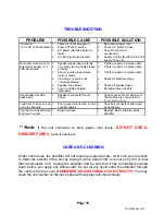
Page 12: ...me or all selected channels on LED illuminated 1 Reconnect power cord 2 Check AC switch or fuse 3 Check for shorts or overloading 4 Supply Control IN with a 5 24 Volt supply Page 5 1 Power cord not pl...

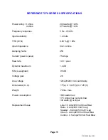
Page 13: ...lew rate 14 V sec Dynamic headroom 1 2 dB S N A weighted 95 dB Voltage gain 28 Line voltage 120 220 240 VAC switchable Dimensions O A 17 w X 19 25 d X 7 25 h Weight 78 lbs max Power consumption 1830 w...

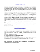
Page 14: ...B K shall not be liable for any incidental or consequential damage arising out of a defect in material or workmanship of the unit during the terms of this warranty or thereafter Some States do not all...

Page 15: ...B K Components Ltd 2100 Old Union Road Buffalo New York 14227 P N 13009 Rev 0102...

Page 16: ...B K Components Ltd 2100 Old Union Road Buffalo New York 14227 www bkcomp com P N 13009 Rev 0102...

Reviews: