background image

Page 14

Connect the wires from your speakers to the appropriate output on the amplifier. 
It is absolutely essential that you observe correct polarity in these connections. 

Example: If you connect your right output of your preamplifier to R channel input on
the amplifier, remember to connect your right front speaker wires to R channel
outputs.  Always observe polarity when connecting speakers, connect amplifiers (+)
to the speakers (+) and amplifiers (-) to speakers (-).   

Double check all connections.

Plug the amplifier’s power cord into the AC power source.  Turn the amplifier’s
power switch ‘on’.  The panel light should be illuminated.  Leave the preamplifier
turned off.  Before proceeding to the next step turn the amplifier off and wait 30
seconds for the amplifier to discharge.  Both the preamplifier and amplifier should
be off.

Connect a playback unit (CD, VLD, Tuner, etc...) to the preamplifier.  Turn the
volume on the preamplifier to minimum. Turn on the preamplifier, then the
amplifier (in that order).  Set source on the preamplifier to the playback unit
you’ve just connected.  Turn volume up slowly and music should be heard from
all channels.  If this is not the case, double check your installation.  

Should you encounter any problems that cannot be traced to the source or the
material being played, consult the “TROUBLESHOOTING” section on


page


15.

Note: When turning equipment ‘off’, the amplifier should always be turned off 

first,

 then

the preamplifier.  When turning equipment ‘on’, the preamplifier should always be turned
on 

first,

 then the amplifier.  

Before turning anything on, ensure the preamplifier is at a

low volume level.

Summary of Contents for ST260

Page 1: ...ST260 Two Channel Amplifier OWNER S MANUAL B K Components Ltd 12997 REV 050500 ...

Page 2: ...B K Components Ltd 2100 Old Union Road Buffalo New York 14227 ...

Page 3: ...ge 5 Control muting Page 5 6 Level controls Page 6 Inputs Page 7 Outputs Page 8 Internal Bus Page 9 Jumper description Page 9 10 Mono application Page 11 Bridged application Page 12 System installation Page 13 Making the connection Page 13 14 Troubleshooting Page 15 Care and cleaning Page 15 Specifications Page 16 Warranty Page 17 Accessories included Manual and Power cord ...

Page 4: ...age can occur to your speakers if the power rating of each individual driver is exceeded by the amplifier Ensure that all the drivers in your speaker system are capable of handling not only the power being delivered by the amplifier but the energy that is likely to be generated during strong passages Turn amplifier off when plugging in or unplugging input and speaker cables The ST260 is equipped w...

Page 5: ...ration With the inputs buffered a line output OUT BUS may be taken from either the L BUS R BUS or L R BUS and sent on to another amplifier This allows for linking of multiple amplifiers Continuing its versatility the ST260 may be used mono to provide one medium current channel in order to drive a speaker requiring more power As a result of the ST260 s unique bus system the input to the left channe...

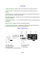
Page 6: ...ors Improve connections for better sound and minimized signal loss and degradation 1 Metal Film Resistors Low noise resistors for better sound and a greater degree of repeatability Medium Current Ability to reproduce demanding recordings Computer Grade Capacitors Large capacity computer grade electrolytic capacitors for extended low frequency control and improved dynamics Rear Panel View 1 AC fuse...

Page 7: ...ote switching of mute on off The preamplifier s control output such as is provided with B K series preamplifiers can be utilized to provide a control signal to the ST260 If more than one amplifier is being controlled the control signal can be extended to include each successive unit by simply running an RCA type audio cable from the CTRL OUT connector of the first amplifier to the CTRL IN connecto...

Page 8: ...Signal IN Sound Signal No Signal OUT Mute No Signal No Signal IN Sound Signal Note The control voltage is for muting control only Each amplifier must be connected to its own source of AC power in order for it to operate Level controls There are two level controls on the back of the amplifier One level control for each channel When using the level controls first start with them turned all the way u...

Page 9: ...s accept line input from the preamplifier s unbalanced output connectors There are two input connectors one for each channel that may be used to connect the amplifier to the preamplifier RCA cable connector Here is a typical input setup You will notice the OUT BUS connections shown above You may use these to connect to another amplifier The L BUS OUT carries the same signal as the L INPUT The R BU...

Page 10: ...gned to accept a banana type plug or spade lug connector shown below and are color coded for easy identification The red post should always be connected to the speakers jack The black post should always be connected to the speakers jack Spade connector Banana jack Here is a typical amplifier setup ...

Page 11: ...annels remove the source control group jumper from its present position if necessary and install it on the terminal you wish to select as the source for that channel Make sure it has been inserted on both terminal pins of the jumper modules To complete the configuration the volume group jumper should be placed at either the USE VOL or NO VOL terminal depending on you configuration Note A channel t...

Page 12: ...ause it is a BUS input any signal input here will appear at the L BUS jumper terminal for both of the ST260 s jumper modules NO VOL If volume control is desired only from the source or if outputs are being combined to obtain higher power the jumper plug should be installed at the NO VOL location USE VOL If volume control is desired at the amplifier beyond that provided at the source a shorting plu...

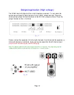
Page 13: ...ut terminals on the ST260 s rear panel must be paralleled in order to complete the setup Simply connect the terminals for both channels together using a jumper wire not supplied with the amplifier Finally connect the speaker cables from the left channels and terminals to the speakers Input your source signal into the left channel input The instructions show the use of the left channel You may also...

Page 14: ... on the NO VOL jumper terminal Place the jumper module on the L terminal Finally connect the speakers to the right channels terminal and the speakers to the left channels terminal Input your source signal into the left channel input only the left channel may be used for bridging Note The default position for this jumper plug is set to the L terminal The jumper plug must be installed at this locati...

Page 15: ...When possible use a separate AC power line for the amplifier one that is not shared by any other component in the system of any other house hold component Tip Take a piece of stout string longer than the longest cable run and mark it at each foot of length Then do a mock cable run using the string dressing it neatly along the way Count the divisions to the next full foot and add one foot to allow ...

Page 16: ...mplifier off and wait 30 seconds for the amplifier to discharge Both the preamplifier and amplifier should be off Connect a playback unit CD VLD Tuner etc to the preamplifier Turn the volume on the preamplifier to minimum Turn on the preamplifier then the amplifier in that order Set source on the preamplifier to the playback unit you ve just connected Turn volume up slowly and music should be hear...

Page 17: ...place cable 4 Check all switch settings Sound lacks direction bass weak 1 Speakers connected out of phase 1 Check connections making sure that cables are connected to and to Loud hum or buzz on one or more channels 1 Poor ground connection in interconnect cables 1 Check all connectors and repair as necessary Channel sounds distorted and low in output 1 Blown rail fuse 1 Replace blown rail fuse ins...

Page 18: ...33 2 k ohms Damping factor 100 Current peak to peak 20 Amps Slew rate 14 V sec Dynamic headroom 1 4 dB S N A weighted 95 dB Voltage gain 28 Line voltage 120 220 240 VAC switchable Dimensions O A 17 w X 12 d X 3 75 h Weight 23 lbs Power consumption 210 watts max 2 3 Amps max current draw 15 watts no input Replacement fuses Line 8 Amp 250 Volt Slow Blow Rails 4 Amp 250 Volt Slow Blow ...

Page 19: ... this warranty and B K shall not be liable for any incidental or consequential damage arising out of a defect in material or workmanship of the unit during the terms of this warranty or thereafter Some States do not allow the exclusion or limitation of incidental or consequential damages and the foregoing exclusions may not apply to you This warranty gives you specific legal rights Your may also h...

Page 20: ...B K Components Ltd 2100 Old Union Road Buffalo New York 14227 716 656 0023 www bkcomp com ...

Reviews: