background image

02

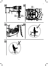
Auxiliary handle (Fig. A)

WARNING! 

For all work with the machine, the auxiliary handle (2) must 

always be mounted. 

Do not make any changes or modifications to the auxiliary handle. 

Do not continue to use the power tool when the auxiliary handle is 

damaged.

1.  Turn the auxiliary handle (2) anti-clockwise to loosen it.

2.  Adjust the auxiliary handle to appropriate position depending on your application.

3.  Turn the auxiliary handle clockwise to clamp it on the spindle collar firmly.

03

Drill bit / chisel (Fig. B)

WARNING! 

•  Observe the technical requirements of this product (see section 

Technical data) when purchasing and using drill bits! 

•  The chuck and drill bits can be very hot after working, do not 

assemble/disassemble them before cooling down!

1.  Clean and lightly grease the shank end of the SDS-Plus drill bit.

2.  Pull the chuck sleeve (2) backward and hold it in position.

3.  Insert the SDS-Plus drill bit/chisel. To insert it completely until stop, combine the 

inserting and rotational motion and find the proper position.

4.  Release  the  chuck  sleeve  (2)  and  check  that  the  drill  bit/chisel  is  securely  fas-

tened. The drill bit/chisel should be locked in the chuck and shall not be possible 

to be pulled out.

5.  To remove drill bit/chisel, pull the chuck sleeve (2) backward and pull it out.

04

Depth stop (Fig. C)

1.  Loosen the auxiliary handle (8) by turning anti-clockwise and insert the depth stop 

(9) through the hole as indicated. The depth stop should be turned to a radial po-

sition so that the tips of drill bit and depth stop have the smallest radial distance.

2.  Align the tip of the depth stop (9) the drill bit tip in axial direction and then pull the 

depth stop back to achieve the desired drilling depth “X”.

16

Summary of Contents for PRH850C

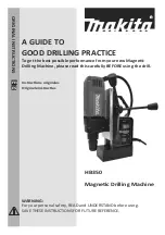
Page 1: ...PRH850C EAN 3663602794790 ORIGINAL INSTRUCTIONS V30318...

Page 2: ...Safety instructions 6 Product description 13 Assembly 15 Use 17 Care maintenance 21 Guarantee 25 Declaration of conformity 26 2...

Page 3: ...1 x1 WARNING Please read all safety warnings carefully and be sure that they are fully understood before handling the tool 3...

Page 4: ...Product description 1 2 3b 3 3a 4 5 6 7 8 9 A 2 1 3 2 B 1 2 2 4 3 1 4...

Page 5: ...C D x 2 1 3 9 8 2 1 3 3b 3a E F 7 90 G 5...

Page 6: ...reduce risk of electric shock b Avoid body contact with earthed or grounded surfaces such as pipes radiators ranges and refrigerators There is an increased risk of electric shock if your body is eart...

Page 7: ...safer at the rate for which it was designed b Do not use the power tool if the switch does not turn it on and off Any power tool that cannot be controlled with the switch is dangerous and must be repa...

Page 8: ...ill Do not drill above shoulder height or below Knee height as the drill cannot be securely held j Never drill holes that are above the declared maximum size in the manual k This drill is not designed...

Page 9: ...oken into very fine dust also known as Respirable Crystalline Silica or RCS during many common tasks such as cutting drilling and grinding Breathing in very fine particles of crystalline silica can le...

Page 10: ...e has been brought in to help reduce hand arm vibration syndrome injuries to power tool users The directive requires power tool manufacturers and suppliers to provide indicative vibration test results...

Page 11: ...sures to protect the operator that are based on an estimation of exposure in the actual conditions of use taking account of all parts of the operating cycle such as the times when the tool is switched...

Page 12: ...fingers going white as well as specific diseases such as carpal tunnel syn drome To reduce this risk when using the product always wear protective gloves and keep your hands warm RESIDUAL RISKS Even...

Page 13: ...ries and damage to property Always wear eye protection Always wear ear protection Wear a dust mask Wear protective gloves Lock to tighten or secure Unlock to loosen Note Remark Caution Warning Wrong C...

Page 14: ...ty Concrete 26 mm Wood 35 mm optional chuck adapter required Metal 13 mm optional chuck adapter required Protection class Weight Approx 4 kg Sound pressure level LpA 88 5 dB A Sound power level LWA 99...

Page 15: ...so includes suitable personal protective equipment WARNING The product must be fully assembled before operation Do not use a product that is only partly assembled or assembled with damaged parts Wear...

Page 16: ...lightly grease the shank end of the SDS Plus drill bit 2 Pull the chuck sleeve 2 backward and hold it in position 3 Insert the SDS Plus drill bit chisel To insert it completely until stop combine the...

Page 17: ...e brick and stone when equipped with SDS Plus bits It is also suitable for coarse drilling operations into wood wood similar materials plastic and metal when using an optional keyed drill chuck Before...

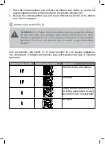
Page 18: ...a complete stop Always ensure that the mode selector is adjusted to the correct position depending on the intended operation Do not use the product with the switch in any intermediate position Turn t...

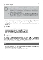
Page 19: ...auxiliary handle status regularly during work refit or replace it if necessary 02 Drilling Drilling into wood wood similar materials plastic or metal could be applied by means of a suitable keyed dri...

Page 20: ...g of the drill bit See Fig F G 2 Always place the drill tip directly on the point to be drilled first and then switch the product on 04 Chiselling Choose a suitable SDS Plus chisel for your applicatio...

Page 21: ...t with high pressure air max 3 bar 4 Check for worn or damaged parts Replace worn parts as necessary or contact an authorised service centre for repair before using the product again Do not use chemic...

Page 22: ...which is coloured blue must be connected to the terminal which is marked with N or coloured black The wire which is coloured brown must be connected to the terminal which is marked L or coloured red 1...

Page 23: ...t it from slipping or falling over Storage 1 Switch the product off and disconnect it from the power supply 2 Clean the product as described above 3 Store the product and its accessories in a dark dry...

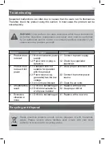
Page 24: ...ct to power supply 1 2 Check by a specialist electrician 2 Product does not reach full power 2 1 Extension cord not suitable for operation with this product 2 2 Power source e g generator has too low...

Page 25: ...an authorised agent Cosmetic damage Damage caused by foreign objects substances or accidents Accidental damage or modification Failure to follow manufacturer s guidelines Loss of use of the goods This...

Page 26: ...e following harmonized standard were made EN60745 1 2009 A11 2010 EN60745 2 6 2010 2014 30 EU Electromagnetic Compatibility directive References to the following harmonized standard were made EN 55014...

Page 27: ...eldon Square London W2 6PX United Kingdom www kingfisher com products Distributor B Q plc Chandlers Ford Hants SO53 3LE United Kingdom www diy com Screwfix Direct Limited Trade House Mead Avenue Yeovi...

Reviews: