Technical data • Complete system
36
Panel PC 2100 swing arm user's manual V1.00
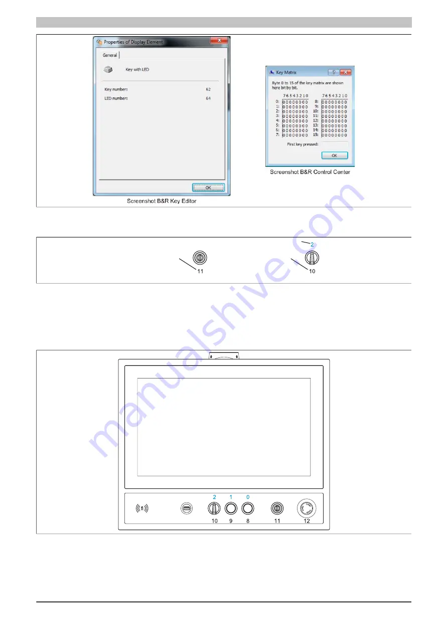
Figure 11: Hardware numbers in the B&R Key Editor and B&R Control Center
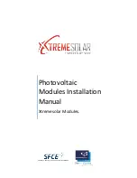
The images below show the positions of buttons and LEDs in the matrix. This information is indicated as follows.
Key with LED
Hardware number of LED
Hardware number of key
Key without LED
Hardware number of key
Figure 12: Display - Keys and LEDs
The configuration below applies to the following display units:
•
5AP99D.185B-00 / -01
•
5AP99D.215C-00 / -01
•
5AP99D.240C-00 / -01
Figure 13: AP99D (landscape) - Button, switch and LED configuration


