X20 system modules • Digital output modules • X20DO2322
X20 system User's Manual 3.10
1077
4.15.4.7 OSP hardware requirements
In order to best use OSP mode, make sure when creating the application that the output module and CPU have
separate power supplies.
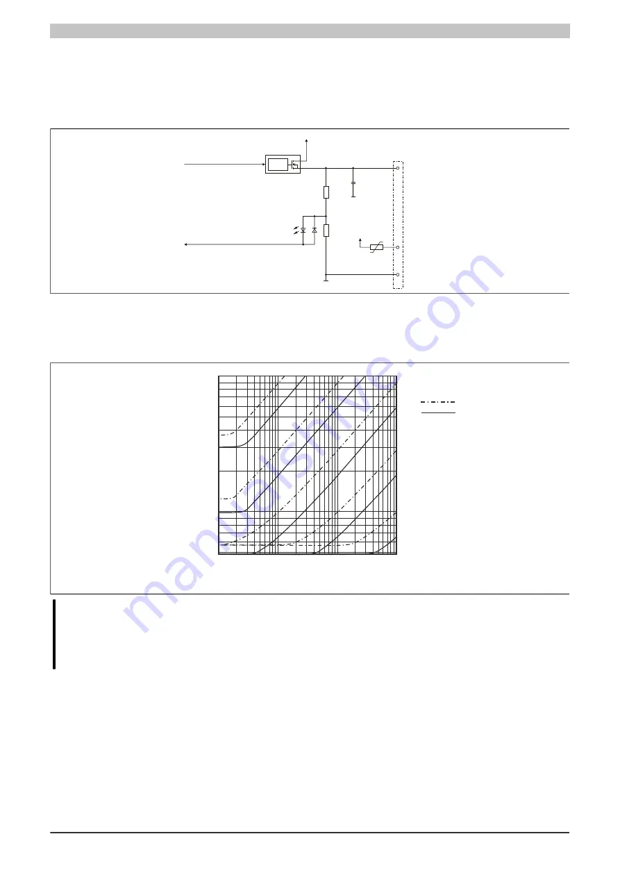
4.15.4.8 Output circuit diagram
Logic
High-side
24 V
GND
Output x
GND
24 V
24 V
PTC
GND
I/O status
LED (orange)
Output
monitoring
Output status
Figure 322: Output circuit diagram
4.15.4.9 Switching inductive loads
Environmental temperature: 60°C, all outputs with the same load
50
0.1
1
10
100
1000
Coil inductance
100 mH
1 H
10 H
100 H
10 mH
Coil resistance
[Ω]
100
Max. switching cycles / second
(with 90% duty cycle)
28.8 V
24.0 V
Switching voltage:
Information:
If the maximum number of operating cycles per second is exceeded, an external inverse diode must
be used.
Operating conditions outside of the area in the diagram are not permitted!
Summary of Contents for X20 System
Page 2: ......


