X20 system modules • Digital output modules • X20DO2633
1094
X20 system User's Manual 3.10
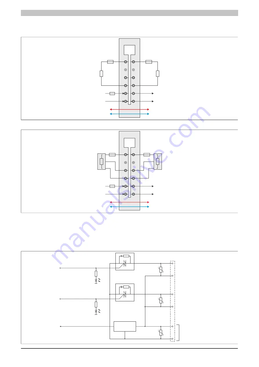
4.15.6.6 Connection example
2-wire connections
GND
+24 VDC
GND
+24 VDC
DO
L
N
L
N
Actuator
Actuator
T 10 A
3-wire connections
GND
+24 VDC
GND
+24 VDC
DO
L
N
L
N
L
N
L
N
Actuator
Actuator
T 10 A
4.15.6.7 OSP hardware requirements
In order to best use OSP mode, make sure when creating the application that the output module and CPU have
separate power supplies.
4.15.6.8 Output circuit diagram
DO 2
DO 1
N
L
N
N
VDR
VDR
VDR
Output status 2
Output status 1
Null
I/O status
(LED orange)
I/O status
(LED orange)
External
Power supply
Zero cross
detection
Summary of Contents for X20 System
Page 2: ......


