X20 system modules • Digital output modules • X20DO4613
X20 system User's Manual 3.10
1159
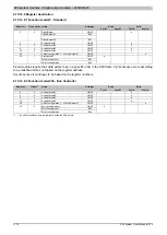
4.15.13.10 Register description
4.15.13.10.1 Function model 0 - Standard and Function model 2 - Frequency mode
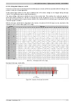
The only difference between function model 2 and function model 0 is the possibility of generating half-wave pat-
terns in various frequencies. Register 18 "CfO_Frequency" is an additional register for this.
Read
Write
Register
Name
Data type
Cyclic
Non-cyclic
Cyclic
Non-cyclic
Configuration - General
2 + N * 2
AnalogOutput0N (Index N = 1 to 4)
USINT
●
18
UINT
●
18 + N * 2
ConfigOutput0N (Index N = 1 to 4)
USINT
●
28
USINT
●
29
USINT
●
Communication
USINT
DigitalOutput01
Bit 0
...
...
2
DigitalOutput04
Bit 3
●
USINT
ZeroCrossingInput
Bit 4
30
ZeroCrossingStatus
Bit 7
●
4.15.13.10.2 Function model 1 - OSP
Read
Write
Register
Name
Data type
Cyclic
Non-cyclic
Cyclic
Non-cyclic
Configuration - General
2 + N * 2
AnalogOutput0N (Index N = 1 to 4)
USINT
●
18 + N * 2
ConfigOutput0N (Index N = 1 to 4)
USINT
●
28
USINT
●
29
USINT
●
Configuration - OSP
Activating the OSP output in the module
USINT
34
OSPValid
Bit 0
●
32
USINT
●
36
USINT
●
36 + N * 2
CfgOSPValue0N (Index N = 1 to 4)
USINT
●
Communication
Switching state of digital outputs 1 to 4
USINT
DigitalOutput01
Bit 0
...
...
2
DigitalOutput04
Bit 3
●
USINT
ZeroCrossingInput
Bit 4
30
ZeroCrossingStatus
Bit 7
●
4.15.13.10.3 Function model 254 - Bus controller
Read
Write
Register
Offset
Name
Data type
Cyclic
Non-cyclic
Cyclic
Non-cyclic
Configuration - General
2 + N * 2
(N-1) * 2
AnalogOutput0N (Index N = 1 to 4)
USINT
●
18 + N * 2
-
ConfigOutput0N (Index N = 1 to 4)
USINT
●
28
-
USINT
●
29
-
USINT
●
Communication
USINT
ZeroCrossingInput
Bit 4
30
0
ZeroCrossingStatus
Bit 7
●
1)
The offset specifies the position of the register within the CAN object.
Summary of Contents for X20 System
Page 2: ......


