X20 system modules • Digital output modules • X20DO8331
X20 system User's Manual 3.10
1261
Product ID
X20DO8331
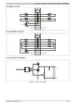
Output circuit
Sink
Output protection
Thermal cutoff for overcurrent or short circuit (see value "Peak short circuit current")
Internal inverse diode for switching ind. loads (see section "Switching inductive loads")
Reverse polarity protection for supply voltage
Actuator supply
Feed
External
Fuse
Required line fuse: Max. 10 A, slow-blow
Diagnostic status
Output monitoring with 10 ms delay
Leakage current when switched off
75 µA
R
DS(on)
35 mΩ
Peak short circuit current
<24 A
Switching on after overload or short circuit cutoff
Ca. 10 ms (depends on the module temperature)
Switching delay
0 -> 1
<300 µs
1 -> 0
<500 µs
Switching frequency
Resistive load
Max. 500 Hz
Inductive load
See section "Switching inductive loads"
Braking voltage when switching off inductive loads
Typ. 50 VDC
Isolation voltage between channel and bus
500 V
eff
Additional functions
To increase the output current, outputs can be switched in parallel
Operating conditions
Mounting orientation
Horizontal
Yes
Vertical
Yes
Installation at elevations above sea level
0 to 2000 m
No limitations
>2000 m
Reduction of ambient temperature by 0.5°C per 100 m
EN 60529 protection
IP20
Environmental conditions
Temperature
Operation
Horizontal installation
-25 to 60°C
Vertical installation
-25 to 50°C
Derating
See section "Derating"
Storage
-40 to 85°C
Transport
-40 to 85°C
Relative humidity
Operation
5 to 95%, non-condensing
Storage
5 to 95%, non-condensing
Transport
5 to 95%, non-condensing
Mechanical characteristics
Note
Order 1x X20TB12 terminal block separately
Order 1x X20BM11 bus module separately
Spacing
12.5
+0.2
mm
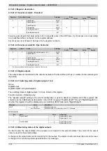
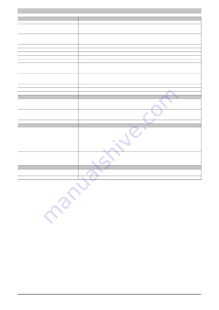
Table 405: X20DO8331 - Technical data
1)
Number of outputs x R
DS(on)
x nominal output current
2
Summary of Contents for X20 System
Page 2: ......


