X20 system modules • Digital signal processing modules • X20DS1828
1370
X20 system User's Manual 3.10
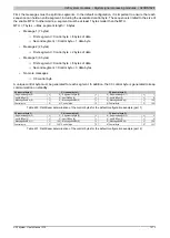
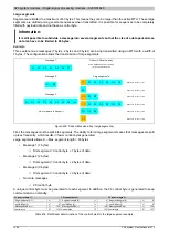
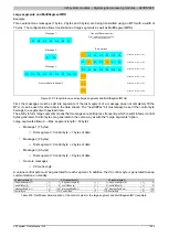
Relationship between OutputSequence and InputSequence
0 - 2
3
OutputSequenceCounter
OutputSyncBit
4 - 6
7
InputSequenceAck
InputSyncAck
0 - 2
3
InputSequenceCounter
InputSyncBit
4 - 6
7
OutputSequenceAck
OutputSyncAck
Outputsequenz
CPU communication status
Input sequence
Module communication status
Intersecting
Handshakes
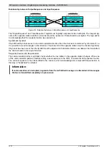
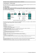
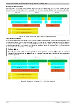
Figure 418: Relationship between OutputSequence and InputSequence
The "OutputSequence" and "InputSequence" registers are logically composed of two half-bytes. The low part sig-
nals to the opposite station whether a channel should be opened or if data should be accepted. The high part is
to acknowledge that the requested action was carried out.
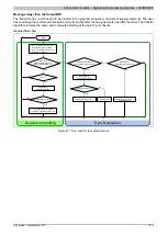
SyncBit and SyncAck
If SyncBit and SyncAck are set in one communication direction, then the channel is considered "synchronized", i.e.
it is possible to send messages in this direction. The status bit of the opposite station must be checked cyclically.
If SyncAck has been reset, then the SyncBit must be adjusted on that station. Before new data can be transmitted,
the channel needs to be resynchronized.
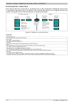
SequenceCounter and SequenceAck
The communication partners cyclically check whether the low nibble on the opposite station changes. When one
of the communication partners finishes writing a new sequence to the MTU, it increments its SequenceCounter.
The current sequence is then transmitted to the receiver, which acknowledges its receipt with SequenceAck. In
this way, a "handshake" is initiated.
Information:
If communication is interrupted, segments from the unfinished message are discarded. All messages
that were transmitted completely are processed.
Summary of Contents for X20 System
Page 2: ......


