X20 system modules • X20 interface module communication • X20IF1063
1800
X20 system User's Manual 3.10
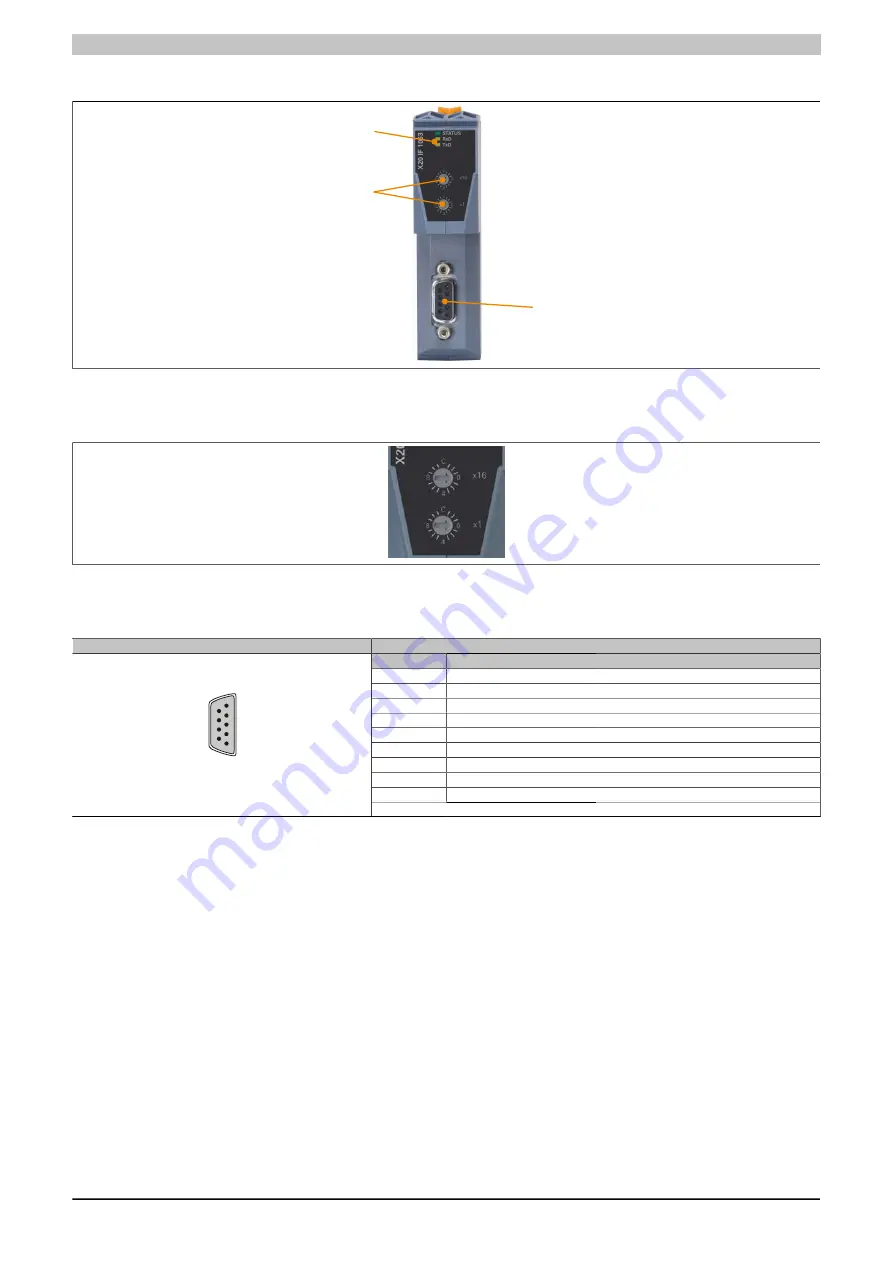
4.23.10.5 Operating and connection elements
LED status indicators
IF1 - Profibus DP
Node number switches
Figure 582: Operating and connection elements
4.23.10.6 Node number switch
The node number for the interface is set with the two hex switches.
4.23.10.7 PROFIBUS DP interface
Interface
Pinout
Pin
RS485
1
Reserved
2
Reserved
3
RxD/TxD-P
Data
1)
4
CNTR-P
Transmit enable
5
DGND
Electrically isolated supply
6
CP
Electrically isolated supply
7
Reserved
8
RxD/TxD-N
Data\
2)
9
CNTR-N
Transmit enable\
1
5
6
9
9-pin female DSUB connector
CNTR ... Directional switch for external repeater
Table 575: Pinout
1)
Cable color: Red
2)
Cable color: Green
4.23.10.8 Firmware
This module comes with preinstalled firmware. The firmware is a component of Automation Studio. The module
is automatically updated to this version.
To update the firmware included in Automation Studio, the hardware must be upgraded (see "Project manage-
ment" / "Automation Studio upgrade" in the help system).
Summary of Contents for X20 System
Page 2: ......


