X20 system modules • X20 interface module communication • X20IF10X0
1858
X20 system User's Manual 3.10
Product ID
X20IF10X0
Environmental conditions
Temperature
Operation
Horizontal installation
-25 to 60°C
Vertical installation
-25 to 45°C
Derating
-
Storage
-25 to 70°C
Transport
-25 to 70°C
Relative humidity
Operation
5 to 85%, non-condensing
Storage
5 to 85%, non-condensing
Transport
5 to 85%, non-condensing
Mechanical characteristics
Slot
Left IF slot on X20CP358x CPUs
Table 644: X20IF10X0 - Technical data
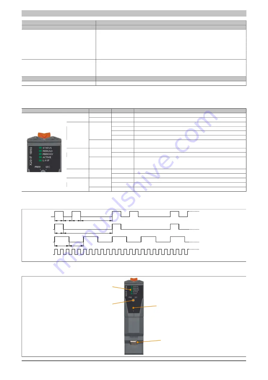
4.23.24.4 LED status indicators
Figure
LED
Color
Status
Description
Green
On
Interface module active
STATUS
1)
Red
Blinking
CPU starting up
On
Possible to failover CPU with hot redundancy
Blinking
Possible to failover CPU with warm redundancy
Double flash
Possible to failover CPU with cold redundancy
Green
Flickering
Application synchronization in progress
REDUND
1)
Red
On
Not possible to failover CPU. No distinction is made here between whether
failover is temporarily or permanently not supported.
On
rCPU = Primary CPU
Green
Off
rCPU = Secondary CPU
PRIMARY
1)
Red
On
Invalid use of the selection switch. One rCPU must be configured as primary,
the other as secondary. It is not permitted to change the switch position during
operation.
On
rCPU actively executing the application
ACTIVE
Green
Off
rCPU inactive
On
Connection established to the redundancy partner
Green
Blinking
Redundancy link active. Data is being transferred for synchronization purposes.
LA/IF
1)
Red
On
No connection to the redundancy partner
Table 645: LED status indicators
1)
This is a green/red dual LED.
250
250
850
150
All times in ms
Flickering
Blinking
Single flash
150
150
150
550
Double flash
4.23.24.5 Operating and connection elements
LED status indicators
Ethernet connection with
duplex LC port
Primary/Secondary rCPU
selection switch
Button
Summary of Contents for X20 System
Page 2: ......


