X20 system modules • X20 interface module communication • X20IF2181-2
X20 system User's Manual 3.10
1861
Product ID
X20IF2181-2
Electrical isolation
PLC - X1
Yes
PLC - X2
Yes
Certification
CE
Yes
cULus
Yes
ATEX Zone 2
Yes
KC
Yes
GL
Yes
GOST-R
Yes
Interfaces
Fieldbus
POWERLINK managing or controlled node
Type
Type 5
1)
Design
2x shielded RJ45 port
Cable length
Max. 100 m between two stations (segment length)
Transfer rate
100 Mbit/s
Transmission
Physical interfaces
100 BASE-TX
Half-duplex
Yes
Full-duplex
No
Autonegotiation
Yes
Auto-MDI / MDIX
Yes
Controller
POWERLINK MAC
Operating conditions
Mounting orientation
Horizontal
Yes
Vertical
Yes
Installation at elevations above sea level
0 to 2000 m
No limitations
>2000 m
Reduction of ambient temperature by 0.5°C per 100 m
EN 60529 protection
IP20
Environmental conditions
Temperature
Operation
Horizontal installation
-25 to 60°C
Vertical installation
-25 to 50°C
Derating
-
Storage
-40 to 85°C
Transport
-40 to 85°C
Relative humidity
Operation
5 to 95%, non-condensing
Storage
5 to 95%, non-condensing
Transport
5 to 95%, non-condensing
Mechanical characteristics
Slot
In X20 CPU
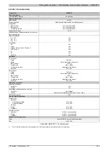
Table 647: X20IF2181-2 - Technical data
1)
See the POWERLINK help system under "General information, Hardware - IF/LS".
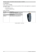
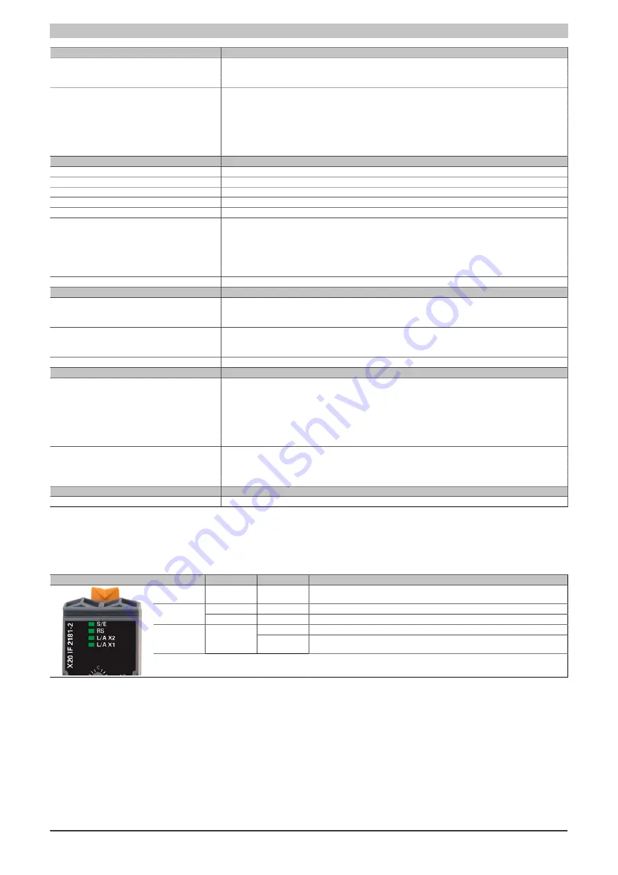
4.23.25.4 LED status indicators
Figure
LED
Color
Status
Description
S/E
Green/Red
Status/Error LED. The LED indicators are described in section 4.23.25.4.1 ""S/
Green
On
Both cable connections are OK.
RS
Red
On
At least one cable connection is faulty.
On
A link to the POWERLINK remote station has been established.
L/A X1/X2
Green
Blinking
A link to the POWERLINK remote station has been established. Indicates Eth-
ernet activity is taking place on the bus
Table 648: LED status indicators
4.23.25.4.1 "S/E" LED
The Status/Error LED is a green/red dual LED. The LED status can have different meanings depending on the
operating mode.
4.23.25.4.1.1 Ethernet mode
In this mode, the interface is operated as an Ethernet interface.
Summary of Contents for X20 System
Page 2: ......


