X20 system modules • X20 hub system • X20ET8819
1894
X20 system User's Manual 3.10
4.24.2.15 Using trigger inputs
The Ethernet analysis tool launches the first connected I/O module in the standard function model. The X2X
bus is configured with a fixed cycle of 1 ms. If this configuration contains digital input data (digital input module
X20DI9371), the first 4 digital inputs will be included in the packet header.
4.24.2.15.1 Background
When looking for very complicated errors, it is usually not possible to find a trigger condition on the network. It is
often difficult to discern whether the cause of the problem is even associated with the Ethernet communication or
somewhere else. The fact that such errors are extremely rare makes finding them that much harder.
A permanent record of network frames through the module X20ET8819 would exceed storage capabilities of the
recording software due to the large amount of data. The trigger inputs on the X20ET8819 offer an additional way
to circumvent this problem. Analysis of the network can be started or stopped when a specific event occurs.
In most cases, the problem can be indicated using a digital signal. The CPU can detect errors or irregularities (e.g.
failure of a network slave), for example, and then set a digital output on the local I/O bus. If this signal is connected
to a digital input on the Ethernet analysis tool, then the module is able to evaluate this information and trigger a
response such as pausing an active recording.
4.24.2.15.2 Evaluation of the inputs on the analysis tool X20ET8819
Input 1 - 4
The first 4 inputs will be inserted only in the packet header by the X20ET8819. The recording software from B&R
(OmniPeek full version and plugin) can determine how the signals are interpreted.
Input 5 - 7
If the recording software is unable to evaluate the first 4 inputs (Wireshark, OmniPeek, various other capture tools),
then inputs 5 - 7 are used to control the Ethernet analysis tool X20ET8819 directly.
Input
Name
Description
5
ExternActivate
Recording will not start automatically if this input is set to HIGH when the analysis tool is turned on. The module waits
for a positive edge on input 6.
6
ExternStart
Recording begins when a positive edge occurs on this input.
The value in 'captureId', offset 49 in the capture frame header is incremented to indicate to the receiving tool that a new
recording has been started. When recording using the recording software from B&R, this information can be used to
switch to a new ring buffer and to store the last one.
7
ExternStop
Recording stops when a negative edge occurs on this input.
8 - 12
-
Reserved
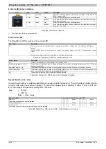
Table 674: Evaluation of inputs 5 - 7 on the analysis tool
Example 1
A drive is started one time each minute. After 10 to 30 hours, a problem arises on a network station shortly after
starting the drive. To analyze the error, the Ethernet communication is recorded between when the start command
is issued and when the error occurs.
Problems:
Due to the large amount of data it is not possible to record the entire 30 hours. Someone would have to stay on
the analysis PC the whole time to stop recording when the error occurs.
Solution:
Input
Description
ExternActivate
Input permanently wired to 24 VDC = Activates the external trigger function
ExternStart / ExternStop
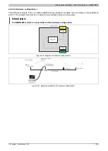
Connect both inputs to the same digital output that the master uses to notify the X20ET8819 when to start and stop recording.
The master can, for example, always set the output before the drive start command and reset it as soon as the startup has been
completed.
When the master detects an error, it only has stop setting the output. This would mean that after 30 hours the recording is certain
to contain the time period in which the error occurred and as well as a few prior recordings of proper startups for comparison.
Table 675: Function of the inputs in Example 1
Summary of Contents for X20 System
Page 2: ......

