X20 system modules • Analog input modules • X20AI2438
X20 system User's Manual 3.10
197
4.3.7.6 Connection examples
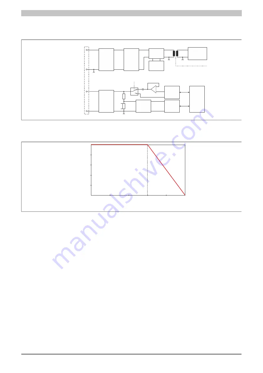
4.3.7.7 Input circuit diagram
Sensor supply x +
Sensor supply x -
Channel x +
Channel x -
A/D
Converter
HART
Modem
Processor
Protection
and
Filter
Input
protection
RTS (Request to Send)
Output
protection
DC/DC
Converter
25 V
DC/DC
28 V
DC/DC
3.3 V
Electrical
Isolation
I/O
Supply
18 - 30 V
Sh
un
t
GND x
GND x
GND I/O
GND x
4.3.7.8 Behavior in the event of a short circuit
In the event of a short circuit, the output current for the sensor supply is limited according to the following diagram.
Current [mA]
0
0
5
10
15
20
25
30
20
10
40
50
Vo
lta
ge
[V
]
Figure 72: Typical behavior of the sensor supply output current in the event of a short circuit
Summary of Contents for X20 System
Page 2: ......

