X20 system modules • Motor controllers • X20SM1436
X20 system User's Manual 3.10
2049
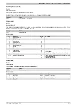
Jolt time
Name:
JoltTime01
If a value other than 0 is assigned to this register, then jolt limitation is performed. This is done by averaging the
values for the steps to be carried out (speed setpoint) in each cycle using FIFO memory. The jolt time corresponds
to the number of FIFO elements (0 to 80). If a value greater than 80 is entered, then it will be limited internally to 80.
Changes made while a motor is running will be applied as soon as ...
•
the motor has reached the position setpoint (positioning modes only)
•
the motor has stopped (all modes)
Data type
Value
Information
0
No jolt time limitation
USINT
1 to 80
1)
Number of FIFO elements
1)
Starting with upgrade 1.3.1.0 (firmware version 16); For older versions: 16
Homing configuration
Name:
RefConfig01
The homing mode can be set with this register.
Data type
Value
Information
-120
Set home position
-121
Homing at positive edge on input DI 4
-122
Homing at negative edge on input DI 4
-125
Homing at positive edge on input DI 3 (R pulse)
-126
Homing at negative edge on input DI 3 (R pulse)
-127
Homing during stall detection
-128
Immediate homing
SINT
Everything else
No effect
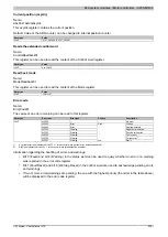
Mixed decay / Stall detection configuration
Name:
StallDetectConfig01
This register sets the ratio between mixed decay and stall detection sensitivity.
Data type
Value
USINT
See bit structure.
Bit structure:
Bit
Description
Value
Information
0
Mixed decay disabled
1 to 14
Steps involved in setting mixed decay sensitivity
0 - 3
15
Mixed decay always enabled
0
Stall detection is disabled
1 to 6
Steps involved in setting stall detection sensitivity
4 - 6
7
Maximum sensitivity for stall detection
0
Motor load value not shown
7
Motor load
1
Show value in register Status word
1)
1)
If this bit is 1, then the motor load value is shown in bits 13 to 15 of the status word register (otherwise these bits are 0). This value can help when testing
Summary of Contents for X20 System
Page 2: ......


