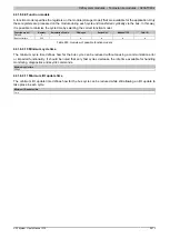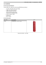
X20 system modules • Terminal blocks • X20TB32
2482
X20 system User's Manual 3.10
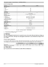
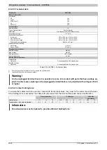
4.32.5.3 Technical data
Product ID
X20TB32
General information
Certification
CE
Yes
cULus
Yes
ATEX Zone 2
Yes
GL
Yes
GOST-R
Yes
Terminal block
Number of pins
12
Type of terminal clamp
Push-in terminal
Cable type
Only copper wires (no aluminum wires!)
Wire stripping length
7 to 9 mm
Connection cross section
Solid wires
0.08 to 2.50 mm² / 28 to 14 AWG
Fine strand wires
0.25 to 2.50 mm² / 24 to 14 AWG
With wire end sleeves
0.25 to 1.50 mm² / 24 to 16 AWG
With double wire end sleeves
Up to 2x 0.75 mm²
Distance between contacts
Left - Right
4.2 mm
Above - Below
10.96 mm
Electrical characteristics
Nominal voltage
240 VAC
Max. voltage
253 VAC
Nominal current
1)
10 A / contact
Contact resistance
≤5 mΩ
Environmental conditions
2)
Temperature
Operation
Corresponds to the X20 module used
Relative humidity
Operation
Corresponds to the X20 module used
Table 901: X20TB32 - Technical data
1)
Take the respective limit data for the I/O modules into consideration!
2)
Identical for operation, storage and transport.
Warning!
On the unplugged terminal block, it is possible to come into contact with parts that have voltage ap-
plied. For this reason, working on the unplugged terminal block is not permitted with voltages of 50 V
or higher.
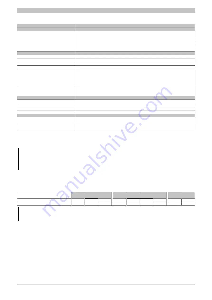
4.32.5.4 Contact holding force
To ensure that cables maintain a secure contact with the terminal block, they must not be under too much stress.
If the holding force is exceeded, the cable will come loose from the terminal block and cause a malfunction.
Fine strand wires
Solid wires
With wire
end sleeves
Cables in mm
2
0.25
1.5
2.5
0.08
0.25
1.5
2.5
0.25
1.5
Standard spec. (min. value in Newton)
12.5
40
50
4
12.5
40
50
12.5
40
Information:
Fine strand wires must be twisted to provide sufficient holding force.
Summary of Contents for X20 System
Page 2: ......

